Turquoise Energy News #211
Covering
Research & Development Activities & Projects of
December 2025
(Posted January 7th 2026)
Lawnhill BC Canada - by Craig Carmichael
[Subscribe: email to
CraigXC at Post dot com ; request subscription]
Main URL TurquoiseEnergy.com Also at craigcarmichael.substack.com
Month
In "Brief" (Project Summaries etc.)
* Solar Power - Solid State Electric Heater - Everlasting
Cheap Battery Developments--Great New Cell Design, working battery
cell - OLAHP: Why It's Better, & Better Indoor-Outdoor Air
Heat Exchanger
In Passing
(Miscellaneous topics, editorial comments & opinionated rants)
* Supplement for High Blood Pressure - Other Supplements -
Scattered Thots - New: Electrosmog Department - ESD
- Detailed
Project Reports -
Electric Transport - Electric Hubcap Motor
Systems - no report (will I ever find time to
finish the next motor?)
Other "Green" &
Electric Equipment Projects
* A New Tech ! Solid State Resistance Heating Elements
made With Power Diodes (advantages over resistance wire)
* Open Loop Air Heat Pumping - New Indoor-Outdoor Air Heat
Exchanger
* Faraday Cabin Construction
New Battery R & D (back in the
news!)
* Organic Copper/Monel Crush Experiment - Promising new
cylindrical cell design - Newer New Cell Design - Organic monel-Zn
cell - Ni-Zn Cell - Ni-Zn cell #2, many tests run, good
performance - Improvements for next cell
Electricity
Generation
* New Grid Tied System - Now In Operation!
* All Systems - The usual Latest Daily/Monthly Solar Production
log et cetera - Monthly/Annual Summaries, Estimates, Notes
December in Brief
 New Battery Cell Design:
"+" electrode outside, zinc/zincate "-" in inner basket
If some of my more
recent reports have seemed to lack much meat in the energy
projects direction, here's a change! I spent much of my time
working on things including everlasting batteries, a solid state
diode space heater, a new indoor-outdoor heat exchanger for OLAHP,
and a couple of things for the Faraday cabin.
And somehow at the start of the month I wrote up
about a bunch of supplements that some may find helpful. Mostly
ones I take. These are commonly available dietary supplements for
various purposes, not medications. I'm not a health professional.
(See "In Passing".) Before the month ended I'd forgotten all about
writing about those!
On my 71st birthday, January first, I could see I was
in for a good week of adding and editing before this report would
be ready to post with most of the mistakes and omissions rooted
out!
Solar Power
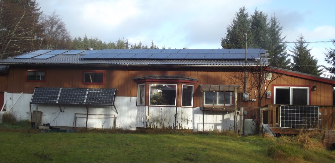 On the 4th I got an email from BC
Hydro authorizing me to turn on the new grid-tied solar system. I
didn't read emails until the evening of the 5th. So... morning of
the 6th I turned it on. I had an AC power meter/monitor. It turned
on in Chinese. Oh crap, did they send me the wrong one? I looked
at the model number, searched, and found a video in Spanish about
how to change it to English. I changed the video to hear it in
English. Aren't translators wonderful? It turned out the power
monitor was also a "smart" circuit breaker that would shut off the
panels on overvoltage, undervoltage or overcurrent - an extra
level of safety.
On the 4th I got an email from BC
Hydro authorizing me to turn on the new grid-tied solar system. I
didn't read emails until the evening of the 5th. So... morning of
the 6th I turned it on. I had an AC power meter/monitor. It turned
on in Chinese. Oh crap, did they send me the wrong one? I looked
at the model number, searched, and found a video in Spanish about
how to change it to English. I changed the video to hear it in
English. Aren't translators wonderful? It turned out the power
monitor was also a "smart" circuit breaker that would shut off the
panels on overvoltage, undervoltage or overcurrent - an extra
level of safety.
Not much was happening for a bit, then current
started flowing. Then the sun came out for a couple of minutes and
the meter said 480 watts, while the "house" off grid system said
200. (Seemed about right - twenty 350W solar panels versus nine
300W.) Then it went back to raining. In fact, the whole month's
solar energy was pathetic, even for December. On top of rain,
overcast, tree shadows and everything, the panels were covered
with snow for a week.
"Overvoltage" was set to just 250 volts. Voltages in the
house are often up to 126, so 252. After it tripped off a couple
of times, I changed it to 265 volts. With snow covering the panels
and then in clouds and rain, the new system produced exactly zero
for weeks. Apparently it needs some threshold to do anything. My
two DC charge controllers were also pathetic most of the time,
often reading "40" or "80" watts instead of the 1500 they can do
in the summer... but they were more than zero. (I seem to recall
the plug-in grid ties usually being more than zero too.) Total for
December from the new system: 36.62 KWH. Less than I've been using
in a day most days in the freezing weather and heating the
upstairs room in the cabin! But November, December and January are
always pretty much "washouts" for solar around here.
Later I got a bill for November until December 3rd.
Seems I'll be on the "self generation" billing plan from the 4th
on.
---
But when the sun did appear, I had noticed that the
solar power system in the cabin didn't seem to be charging as well
as it should, even for December. Putting the charge controller on
the outside wall made for about a 35 or 40 foot run of #10 AWG
cable from it to the battery. A voltage drop of (say) 1 volt
doesn't mean much most places, but it means the charge controller
is only putting 39.8 volts into the battery instead of 40.8, and
LiFePO4 cells have such flat voltage curves that that means a much
lower charging current is flowing, and solar potential power is
being wasted. (40.8 volts with no load is 100% charge.)
[5th] It was only getting 370 watts and saying 40.0 volts, but I
suspected the charge controller was putting out the set maximum
40.8 volts. I turned on a 250 watt heater. The voltage dropped a
bit but the charging rose to 465 watts. So, there Was more solar
available, but not being used!
[6th] Rather than switch to costly, stiff #6 cable - or move the
36 volt DC electrical service to the wall where the charge
controller was - I decided to turn up the controller by three
notches from 40.8 volts to 41.7. 42.0 volts is the highest
recommended charge voltage. I think lower makes the batteries last
longer, but it'll only get up to 41.7 if the battery is really
well charged and not much current is flowing, ie, in the summer. I
don't expect to see the battery over 41.0 (if that) in the winter
when I'm trying to run electric heat. The sun had come out again
and the result was immediate. Where I hadn't seen over 400 watts
in weeks, it now read 670!
Well, one system at last in service, another
improved. Things are looking up! And the sun will return.
Solid State Electric Heater
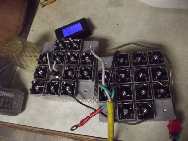
I got 60 power bridge rectifier diodes and laid out
25 on two heatsinks for a 36 volt DC heater, and another 25 on an
alume plate for a 36 V electric 'hotplate' or 'burner'.
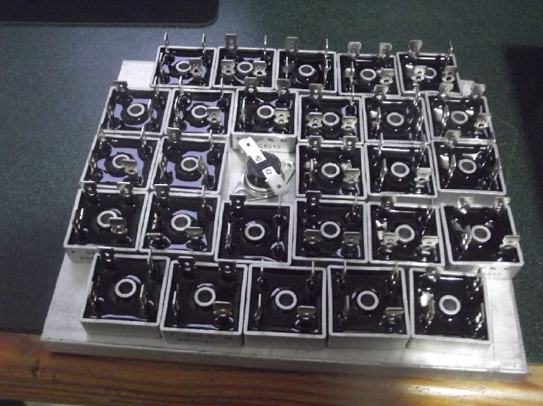 First concept, for a burner/hotplate.
Underside view.
First concept, for a burner/hotplate.
Underside view.
Later I got a somewhat bigger plate and dropped to 25 bridges.
I didn't find time to pursue it further. (Yet)
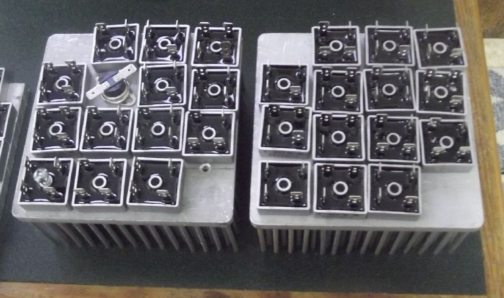
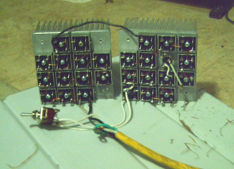
The solid state heater concept, with two 5 by 5 inch heatsinks.
This one I built.
 I put together the heater elements
and got it working. I tested it on the kitchen counter using the
36V DC outlet I had wired under the kitchen sink.
I put together the heater elements
and got it working. I tested it on the kitchen counter using the
36V DC outlet I had wired under the kitchen sink.
 Per my vague
expectations (but not even mentioned in the bridges' datasheet!),
the forward voltage drops reduce with temperature, so the hotter
it got, the more current flowed - a pronounced positive feedback
loop. It took a while to "ramp up" from around 1 amp (40 watts) to
21 amps (720+ watts) and 120° C, which was about where the
temperature switch cut it off. Then it would cool down for some
minutes and come back on again for another run. I kind of expected
the circuit's 20 amp DC breaker to blow just before it cut out,
but it never did. I added another diode drop with 1/2 of a 26th
bridge. Then it went up much more slowly and only got to under 600
watts before it shut off. So I put in a HI-OFF-LOW switch for
50-[off]-or 51 diode drops.
Per my vague
expectations (but not even mentioned in the bridges' datasheet!),
the forward voltage drops reduce with temperature, so the hotter
it got, the more current flowed - a pronounced positive feedback
loop. It took a while to "ramp up" from around 1 amp (40 watts) to
21 amps (720+ watts) and 120° C, which was about where the
temperature switch cut it off. Then it would cool down for some
minutes and come back on again for another run. I kind of expected
the circuit's 20 amp DC breaker to blow just before it cut out,
but it never did. I added another diode drop with 1/2 of a 26th
bridge. Then it went up much more slowly and only got to under 600
watts before it shut off. So I put in a HI-OFF-LOW switch for
50-[off]-or 51 diode drops.
I didn't experiment with this long enough or through
supply voltage ranges to draw sure conclusions about the heat
turning down if the battery was low. It did seem to "ramp down"
when turned from high to low at whatever voltage was there. (It
doesn't help measuring that the supply voltage drops as the load
increases and vise-versa.)
But later I did find that it had turned itself down
to almost nothing overnight when set on "LOW". Seems the battery
voltage got down a bit in the night. I think it shut down too soon
- there was lots of battery left. On "HIGH" it would have
extracted more before doing the same thing.
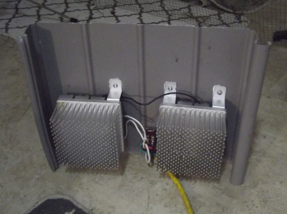
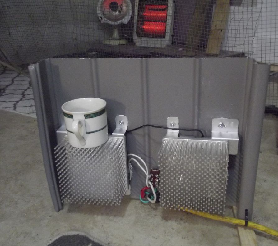 Then I mounted them on a scrap piece of alume
siding. It seemed to stand up nicely all by itself, and the siding
became an additional heat radiator. [More in the detailed report.]
Then I mounted them on a scrap piece of alume
siding. It seemed to stand up nicely all by itself, and the siding
became an additional heat radiator. [More in the detailed report.]
It would seem that the solid state diodes heater has these
advantages or features:
* Unlikely to kill the battery if it runs low with the heater left
on (my original attraction to the idea). One night I put it on
"Low" (51 diodes) and in the morning found it virtually cold - the
battery had got a bit low for 51 and the power had "ramped down"
to around 40 watts. Switched to "High" (50 diodes) the power and
heat started ramping up again. If the voltage had been (.7?) volts
lower, "High" would also have turned itself down to "not much".
* Safer: The heat is diffused through the unit. The hottest parts,
the diode bridges, are "inside" and also don't get hotter than
about 125°C. Even without safety shielding no one will get a
sudden nasty burn from an accidental brush.
If the heater gets blocked or covered, it will still
only get up to 120°C before shutting off. I don't think that's hot
enough to start a fire. I set a small piece of tissue paper right
on top of one heatsink and its diodes, partly blocking the
airflow. It didn't do anything. It didn't turn brown or catch fire
in a few hours. (It didn't even keep my coffee hot!)
* The lower temperatures may make for less drying out of the air,
a negative feature of many electric heaters. (...or is that just
from any heat with no air inflow, period?)
* Being solid state except for the thermal cutout switch, it's
likely to last a long time and not burn out.
Of course, being 36 volts, this one isn't going to
shock or electrocute anyone even with bare terminals exposed. Ya,
of course it should have a screen over it anyway. It should also
have better thermal conductivity from the heatsinks to the
chassis/plate so that would get warmer before shutting off. (Then
it would run longer and the average watts would go up. A fan would
of course have similar effect.) But it's just a prototype and I'm
pleased that it works rather nicely for me.
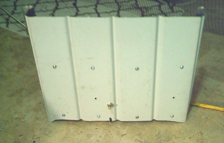 The back of the heater with the
High-Off-Low switch.
The back of the heater with the
High-Off-Low switch.
The last refinement was to cut the shallow bottom arch so that
only the cooler
outside edges touch the floor, and convection can draw air
through under the middle.
(If I had mounted the heatsinks higher up I could have made the
arch taller.)
New Chemistry Batteries - and the New Cell Design
Chemistry is one thing, but the new
battery cell design is the real wonder worker, the "game changer".
There's no stresses on the carefully prepared ion-blocking
separator sheet during assembly. I can compact electrode
substances reasonably well during assembly and they should stay
reasonably well compacted. A big graphite sheet current collector
wraps around the perimeter for making fairly thin electrodes,
valuable with the less conductive positive electrode formulations.
And the solid plastic ointment jars won't leak!
With these various problems solved I seem to be able
to make batteries that actually work according to plan. Finally I
can concentrate on what goes into the cell, try out different
electrode substances and things, without having various problems
with the mechanical aspects to mess it all up.
With the 'organic chelated copper'-zinc cell
performing but poorly, I got frustrated and decided to try
something that really ought to perform if all my zinc improvements
did: nickel [oxyhydroxide]-zinc, using the nickel substance from
an old Ni-MH "D" dry cell. If somehow offered some opportunity
before getting the organic mix (or else nickel-manganese oxides)
working well, I wanted to be able to say with confidence, "Yes, we
can make great, long lasting batteries! I have proven everything
needed works." But the dry cell mix was designed for pH 14, and it
actually didn't work so well until I raised the pH from the 13
I've been using for some time now to 13.5 with extra KOH. After
that it started holding a charge.
A problem I kind of waved aside now showed
itself as more troublesome than expected. The metallic zinc side
started as metal - fully charged. The nickel, OTOH, had been
sitting for years and was dried out - fully discharged. The Ni-Zn
cell started out 10 times better than the "organic chelated Cu"-Zn
-- but still pathetic. In a few days of charging and discharging,
however, it was much better. Each cycle, running it down to almost
nothing and charging it again, was better than the previous one. I
kept increasing the load, from 100 ohms to 50 to 25, but the
running times got longer faster than I was dropping it. Unlike
most (if not all) of my previous cells over all these years, I
didn't note any sort of deterioration except loss of liquid, which
was to be expected in this process and without good seals. It went
from delivering a few milliamp-hours on the first try to 125 (25
ohms, in 3 hours) by the sixth day. It works, but it's very
tedious.
So I started experimenting. One could either use
zincate solution (discharged) instead of zinc metal, or chemicly
charge up the nickel. IIRC putting the substance in bleach will
charge it. Instead of water, I put in a cc of sodium hydroxide
zincate I had on hand to top up the cell, to speed things up. It
did seem to help.
I got some better tests, but finally I opened "Ni-Zn
cell #2" and re-compacted the nickel material. Then it ran longer
and would drive a 10 ohm load, and short circuit current went up
to 100 mA/sq.cm, which is reasonably good and better than I've
achieved before.
I discovered that while silver would soon oxidize,
gold remained inert and shiny even with the high voltage of a
nickel oxyhydroxide electrode. (Hey! I thought Jungner had tested
ALL the metals around 1900 and found that only nickel would work
in alkaline cells!?! That's what everybody has said ever since -
"only nickel"!)
Pure gold is expensive and of course if there's any
breach in a plating to a susceptible metal underneath, that metal
will eventually disintegrate. Which leaves gold plated graphite.
Graphite won't corrode and it's conductive enough internally, but
surface contact to anything else is generally poor. Plating it
with even an invisibly thin skin of gold should make for excellent
connections and high currents.
Silver plated graphite should work with lower voltage
electrodes.
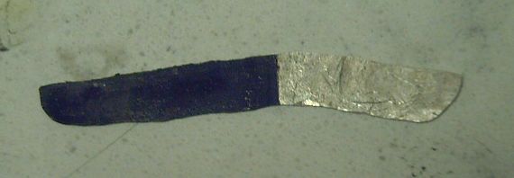
A silver strip I tried for a positive
electrode terminal.
At the high "+" voltage of NiOOH the surface of the immersed
part oxidized to black Ag2O.
A gold strip however has remained clear and shiny. Wow!
I've never seen that in any literature anywhere! Has no one
ever tried gold before?!?
Next cell plan:
Zinc sheet "-" wrapped around copper wire center,
Silver sheet "+" current collector & terminal at rim,
for Organic-monel "+" electrode substance.
Into January "Ni-Zn Ointment Jar Cell #2" was still
performing very well after over 3 weeks - even improving. Surely
the best cell I've made. Even with only 15 sq.cm. electrode
interface surface it will drive a 5 ohm load, around 280 mA, with
only moderate voltage loss, around .2 volts. The chief remaining
weakness of my cells is that they lose electrolyte: it wicks up
the terminals and evaporates outside. That's why my alligator
clips get all corroded. Along with frequent watering I've now had
to add 2g of KCl salt and 1g of KOH. Modelling clay doesn't seem
to fix it. So far I don't want to really seal them up (beeswax,
heat glue...), as I still want to be able to open them easily to
look inside.
OLAHP - Why It's Better - & Better Indoor-Outdoor Air Heat
Exchanger
First of all, I'm not sure I've successfully conveyed
in the past why open loop air heat pumping (OLAHP) is
fundamentally far superior to today's refrigerant based heat
pumping, so I'm going to take another stab at it. Here's the
essential short version:
* Today's Refrigerant based heat pumping: COP is 1 to 5,
decreasing with outdoor temperature; 100 to 500 watts of heating
for each 100 watts of electricity.
* Open Loop Air heat pumping: COP is around 10, almost independent
of outdoor temperature; 1000 watts of heating for each 100 watts
of electricity.
Here's the more involved description:
"The experts" may say that the coefficient of performance ("COP")
drops with decreasing outdoor temperature, and that attaining a
high COP such as 10 in freezing weather or below is theoreticly
impossible. But they are thinking inside a box.
Let us assume outdoor temperature is -5°C, which is
268°K. In a refrigerant based heat pump, refrigerant is brought in
from the outdoor unit at outdoor temperature. The purpose of the
outdoor radiator-fan unit is in fact to bring the "super cooled"
refrigerant back up to [almost] outdoor temperature. The
compressor heats it from there up to a radiator temperature
where air can be blown through the radiator fins to heat the
indoor space, say 35°C or 308°K. (We assume the indoor space is
about 21 to 23°C.)
The potential COP equation is:
Initial°K / (Final°K - Initial°K), [or (final - initial) in °C -
same thing]
or
Initial°K / (temperature rise or "lift"° [C or K])
So the maximum COP is:
268 / (308-268) = 273/40 = 6.7
An actual system might generously attain around half the
theoretical potential value or COP = 3.4. From my understanding
that would be excellent if not amazing performance at minus five
degrees outside.
In the OLAHP system, the compressor heats air from
[slightly below] room temperature to the same 35° radiator
temperature. Call it 20°C or 293°K. The COP equation then
becomes:
293 / (308-293) = 293/15 = 19.5
The key is that the compressor is heating the "refrigerant" (air)
by only 15° instead of 40°. And the starting temperature is
higher, 293° instead of 268°. Again allowing for about 50%
efficiency, the attainable COP = 9.75 -- 10 rounded off: 1000 W of
space heating for 100 W of electricity. With commercial
development, even higher than 10 might be achievable. Cooling
could of course be done similarly. What would that do to reduce
global and individual energy consumption?
The key to being able to start with 20° air is the
passive indoor-outdoor air heat exchanger. After the
compressed air has gone through the radiator and delivered its
heat to the space, it is down to [just above] room temperature. It
is then fed into the exchanger's piping, still compressed. As it
travels along its length, it gradually gives up its heat to the
incoming uncompressed air from outdoors. At any point along the
length of the exchanger the outgoing air is a little warmer than
the incoming, and is heating it up bit by bit until at the far end
the compressed air is down to [just above] outdoor temperature,
and at the near end, the incoming air has been warmed to [just
below] room temperature - our 20° figure. This is already common
practice in "heat recovery ventilation" except that our outgoing
air is in piping, compressed, which makes efficient heat exchange
easier. This passively warmed air is what is drawn into the air
compressor, not "raw" cold outdoor air.
The still compressed air, now down to [almost]
outdoor temperature, is then fed into a pivoting vane air
engine on the same shaft as the pivoting vane rotary
compressor shaft. Its remaining compressed energy helps turn
the highly efficient compressor, for the ultimate of efficiency.
Finally the air comes out of the air engine decompressed, and is
vented outside. At this point it is well below outdoor
temperature. It is vented away from the intake so it doesn't have
to be reheated to outdoor temperature. The only "outdoor unit" is
the outdoors environment itself. This is the "open loop" part of
the system.
So we have taken 20° room temperature air, compressed
it until it reaches the radiator at 35° where it releases its heat
to the room, then that "spent" air feeds the exchanger and comes
out at outdoor temperature, then the "doubly spent" air helps turn
the compressor before being discharged outdoors uncompressed at
maybe -15°C, "triply spent". So after heating air by only 15° with
the compressor we have extracted 50°, all of which is in some way
used to help heat the space.
As long as the compressor and radiator are adequate,
the space is heated at any outdoor temperature. And as long as the
indoor-outdoor heat exchanger isn't overwhelmed by extreme cold
and too-high flow rate it delivers air from outside at near room
temperature, so there is little theoretical decrease in COP
regardless of the outdoor temperature. It can still be near COP 10
when it is -20° outside - again provided the exchanger is
adequate.
What little COP decrease there will be with dropping
temperature will mainly be attributed to the air engine receiving
less compressed air volume because that air is colder.
Compared to today's systems, this is almost FREE heat in any
weather! Now onto the month's endeavors.
The Better Indoor-Outdoor Air Heat Exchanger
I had considered that the radiator elements from
refrigerant based heat pumps would be good for indoor-outdoor heat
exchangers except that they were set up for a single temperature
difference, whereas the exchanger needs a gradual increase in heat
from outside air up to (almost) room temperature as it travels
inward, driven by a gradual decrease in inside air temperature as
it travels outward heating the air coming in.
I took a new look at them and realized I could
disassemble them down to the individual radiator elements, which
could then be arranged in a linear progression with baffles to
force the incoming air back and forth across the fins as the air
compressor sucked it in. The outgoing air, having spent its extra
heat to the room, is still compressed and goes out oppositely
through the tubes until it is (almost) at outdoor temperature.
The exchanger is paramount to getting high
coefficient of performance (COP) from the open loop air system,
and this should work much better than what I have been using, so I
decided it's worth making and trying out. Maybe I can get it up to
COP 5, 6 or 7 in freezing weather even without the special air
compressor and "air engine". 600 or 700 watts from a 100 watt
refrigerator compressor - or 900+ watts with a 150 watt compressor
- would go a long way toward making my kitchen warmer in winter!
(COP 10 = 1000 watts from 100 watts with all the components built
and working would be even better of course!)
Idea for baffling in ducts to force
air to flow across radiator fins.
3D printed baffle pieces?
I disassembled a heat pump radiator and extracted the heat
exchangers.
I cut off all the convoluted ends right at the first fins with
the angle grinder,
then started plucking off a bunch of fins to access the pipe
ends.
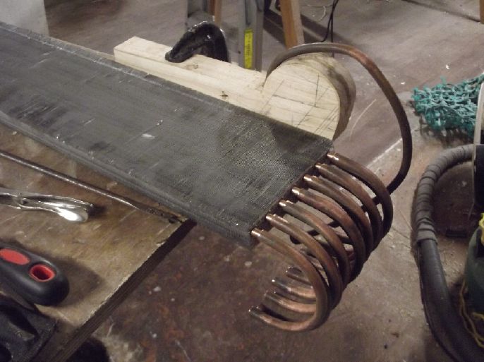
I got as far as making 14 U-turn pipes to connect the pipes of
the two large heat exchangers.
(I think those two will be sufficient to invoke the law of
diminishing returns without adding more.)
A "linear" arrangement doesn't mean the line can't be folded
over to take up less wall space.
I cleaned the bent pipes in hydrochloric acid. I expect
soldering will nonetheless be a challenge.
In Passing
(Miscellaneous topics, editorial comments & opinionated rants)
HIGH BLOOD PRESSURE - ARTHRITIS & OSTEOPOROSIS - SOME
SUPPLEMENTS
HIGH BLOOD PRESSURE
My friend Ian, who has done various work in health
related fields and who told me 15(?) years ago that boron
deficiency had been discovered to be the common cause of
arthritis, reports finding a herbal treatment for high blood
pressure. [My own blood pressure has been 120 over ~80 for decades
so I have no need or "opportunity" to check this out myself. But I
know many older people have high blood pressure.]
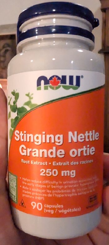 "The treatment for high
blood pressure is stinging nettle root extract. I buy the capsules
because they represent a large amount of herb per capsule. 3 g
actually per capsule.
"The treatment for high
blood pressure is stinging nettle root extract. I buy the capsules
because they represent a large amount of herb per capsule. 3 g
actually per capsule.
I did three to six of those capsules to allow myself
to discontinue the pharmaceutical. In the absence of the
pharmaceutical my blood pressure skyrockets but the herb can
prevent this and allow myself to withdraw. So far I'm down from
three a day to two a day and my energy has gone way up."
(This isn't the stated purpose on the jar. But if it works, it
works.)
I've also just watched a video comparison of grains
wherein the presenter specificly lists khorasan/kamut wheat (and
not any other grain) as very good for lowering blood pressure.
There was however no indication of preparation of the kamut for
food, such as cooking it whole or ground as flour in bread.
Kamut is also the variety of wheat that seemed to
grow best in my garden on Haida Gwaii, and with kernels twice the
size of other wheat kernels.
ARTHRITIS & OSTEOPOROSIS
Again thanks to Ian... I've said this before, but it's worth
repeating... The common cause of arthritis is boron deficiency, so
the usual cure for most cases of arthritis/osteoarthritis, and
osteoporosis, is
(a) boron citrate pills, 3 milligrams daily (Do Not use boron
glyconate! Also beware of pills with only an insufficient amount
of boron citrate, eg, I've seen 800 microgram pills.)
or
(b) common "20 Mule Team Borax". I put a 'heaping' teaspoon of it
(4 to 5 grams) in a pint of water (= 2 tsp/litre), shake it up and
keep it in the fridge. Drink just One or Two Teaspoons of this
liquid per day. (It is only a Trace mineral! Any slight impurities
in the borax are just a trace of a trace. Ian once looked them up
and found there were just minute traces of harmless salts.)
Many people have cured their arthritis with both
these methods. Borax is cheap, but pills are more convenient. It's
said to take 2 or 3 months to take effect, but some people have
noticed more rapid improvement. (One even said relief in her
fingers from the borax was immediate! - surely an anomaly.) There
is a precedent of "borax tea" - it was once popular in England. I
don't know how it was prepared. "Tea" suggests too much borax all
at once, but probably it did relieve arthritis.
It seems the body delivers calcium to the joints to
go into the bones from the more porous ends, but with boron
deficiency the delivery ends or is reduced there. So the calcium
builds up in the joints (arthritis) and doesn't get in to
strengthen the bones (osteoporosis). (We get various deficiencies
because our unsustainable agricultural methods don't replace most
trace minerals and the soil has become depleted. The nutritional
value of many or most of our foods is way down from what it was in
1950. For one thing, our bodily wastes need to get recycled into
the soil rather than "disposed of".)
My mother once fell a couple of times and fractured
the sacrum in her hip. (Age ~80.) After it had healed they decided
to do a "hip replacement", but it was several months before they
got her in. In the meantime I had got her taking the 3 mg boron
citrate pills for two or three months. After the surgeon did the
work he told my mother she had very strong bones. I think the
surgery was completely unnecessary.
I ran this by Ian in an email, and found he had
somewhat different and quite exact ideas about doses and taking of
borax. He's the expert and no doubt there is an optimum. Also he's
using the borax to help clean his teeth! Here is what he said:
"I see two corrections to what you put down. If you're going to
use the boron capsules, you need to take two or three of those
capsules a day, for a total of either six or 9 milligrams daily.
"Mixing your own Borax: The correct formula is 18 g
of (20 mule team) Borax in exactly a liter of water.
"When you work out the molecular weights then each CC of
this liquid contains exactly 2 mg of boron. To use this liquid
you need to dissolve it in hot water, not cold water because
it's a slightly supersaturated solution.
"Once you've got the solution, you use a 5cc syringe which
you can get for free from the drugstore for liquid medicines. I
recommend squirting it in your mouth and swirling it around to
help your teeth. In research with rats, they scratched the rat's
teeth and then washed with the borax solution and the rat
quickly replaced the scratch with fresh enamel. Not sure if this
happens but it does kill tooth decay bacteria."
(FWIW, my 'formula' of "a teaspoon of borax in a pint of water" =
~5 grams in 1/2 a liter or 10 grams per liter - is half as
concentrated and so not supersaturated. A teaspoon holds 5 to 6 cc
of liquid, so two teaspoons is about the same as Ian's dose
recommendation.)
SOME OTHER SUPPLEMENTS
There are other supplements of things that we may not get good
levels of in our food, because of poor soils or regardless. Here
are some I take, probably in decreasing order of importance. (and
the amount I take) This is just my own list, and I'm not a health
professional. On the plus side, people usually think I'm younger
than I am. I told a friend I was 70. He said "You're in good shape
for 70. He*l, you're in good shape for 50!" The supplements surely
help. Read it for what it's worth.
* Vitamin D3 (1000 IU). This cuts the risk of cancer in half, and
cancer is one of the leading causes of death. Tests show that MOST
people don't get enough sun and are seriously vitamin D deficient.
Not to the extent of getting rickets, but by enough to greatly
increase our risk of a number of diseases including cancers,
influenzas and covids.
* Melatonin (5 mg). It is said that we don't make enough of it
after around age 40. The first book I read on supplements listed
2.5 grams after age 40 as #1 on his list. The body makes the most
in the early hours of the morning during sleep, and so I take it
when I get up in the morning. Others take it before bed - it's
supposed to help one get to sleep.
* Borax as per the article above.
* Creatine (half a scoop - the scoop or spoon comes in the jar.)
This is said to be very helpful for older people to keep up their
strength and muscle mass. I've recommended it to people who have
trouble getting around, and (from age 65) I've been taking it. It
also comes in pill form. On "SciShow" on youtube it was #1 of "Six
Supplements That Are Actually Beneficial" (as best I recall the
title).
* Vitamin C. Apparently Linus Pauling was right - at least half a
gram to a gram daily if you're not getting plenty in your diet.
Vitamin E is said to go along with it, at least 100 mg. Most
vitamin E pills are 400 mg; a few are 200.
* Gingko Biloba (also spelled "ginkgo" but not pronounced that
way. One pill.) The bilobate leaf of the gingko, the oldest living
tree species (dating from the Permian period before the dinosaurs
- not long after the first Glossopteris seed ferns first provided
a good food source for a land based ecology). Evidently helps
build new capillaries. Said to help with memory. Seems to help me
with remembering there was a reason I wandered out to the shop or
whatever, instead of wandering back into the house and then
remembering and having to go again.
* Potassium Bromide powder (KBr, 100 mg - "a pinch of") Reduces my
"familiar tremors". Another thing we probably don't get enough of
in our food any more. As I recall I couldn't write without jitters
in my late 50's. My dad could hardly hold a cup of coffee by the
time he was in his late 70's. I know (knew?) a lady who's similar.
I gave her some and explained, but I haven't seen her since to see
if it's helping.
Some have said that bromine has no biological
function, but this can't be true. Probably its function just
hasn't been identified. We do get a small amount of it in our
food, but ones or low tens of milligrams per day. KBr is used to
prevent convulsions in dogs, and it used to be used (1800's) for
its tranquilizer effect in people. The dosages used for that were
far higher - 2 or 3 grams per day, and that caused mental health
issues, so this use dropped out of favor. I don't get much more
than a gram in two weeks. Apparently it's just enough to help damp
out involuntary twitches and shakes. Not that it's "perfect", just
"a lot better much of the time".
* Ginseng (1 pill - "Organica Siberian Tiger Ginseng") Also helps
with tremors. I found this one before the KBr and I still take it.
Pretty sure they both help. I mention the brand I use because
early on I tried others that didn't help as much. I hope they
don't run out of Siberian tigers!
---
* Sumatriptan (1/3 to 1 whole pill as required). This isn't a
supplement for regular consumption, it's a medication for migraine
headaches when I get one. I'm very prone to getting them from all
but the freshest food - from food that most others have no trouble
with, also from food with particular unhealthy ingredients. MSG is
an example that will give a migraine to most anyone who is
susceptible to them. Sumatriptan usually makes a migraine simply
vanish in a half hour or so as if it had never been. They seem to
last about twelve hours, and by that time the cause of the
migraine is - usually - gone from the system. Life has been much
more worth living since these were invented in the 1990's and my
brother introduced me to them. By prescription (Outrageous -
Why?). Prices vary widely, presently from around 3.50 to 13.00 $
per pill, so shop around. I generally go through 4 to 6 of these
per month. Sometimes I go for weeks without needing one, sometimes
I've got some bad food or something that I don't identify very
quickly and I'm popping them like candy, even a couple a day.
(Last one: one particular type of corn chips was causing me
headaches. I bought and ate 2 or 3 one Kg bags before I figured
out what it was. "Surely it's not the chips! I don't get headaches
from unflavored chips!" "I guess the salsa has gone bad." and I
feed the salsa to the chickens. probably a couple of jars, to no
avail. Now I've accidently bought more the same chips (the bag is
similar to another) and am feeding those to the chickens.)
Scattered Thots
* Chiropractor Harold J. Reilly, author of "The Edgar Cayce
handbook for Health Through Drugless Therapy" (a worthwhile read!)
was asked "Which are the best exercises?" He replied "The ones
that you do!" That's my philosophy on supplements as well.
If our foods were nutritious we'd probably be getting most of what
we need - in considerably varying daily amounts.
* Is exercise a waste of your time? A 100 year old doctor said you
would live three hours longer for every hour of exercise you get.
You could probably argue with doctors about many things, but it
would be hard to argue with a 100 year old one about longevity!
* Specific health problems generally have specific, discernable
causes, but very often they never are discerned and people suffer
and die from remediable but unknown - unrecognized - causes. A
doctor doesn't see patients except in the office, so he doesn't
see what the patient is doing or suspect the cause. He only sees
the effect.
For example, someone I once knew was having severe
problems with his esophagus. It occurred to me later that he loved
to drink scalding hot tea. He was scalding his throat daily,
probably multiple times! He's probably long gone now, from that
cause. Had I been more astute back then I might have connected the
dots. He hadn't. His doctors didn't know why he was having the
problem.
* My butter is so hard even left out on the kitchen counter that
it's frustrating to use. I've often been pulling the soft
margarine out of the fridge in preference. I chalked it up to my
cold kitchen in winter. Apparently that's not it. Across the
country everyone has been noticing it. Someone decided that
Canadian dairy cows should be fed palm oil. Seems that's what's
making the butter so hard even at room temperature. Probably it's
just as healthy. But I bet they never thought it might drive
people to margarine!
* My new AC power monitor (for the new solar power system) started
up in Chinese! I looked at the model number on the box, searched
for that, and found a Spanish (Mexico?) video about how to change
it to English. I turned on 'captions' and they too were in
Spanish. I went into video 'settings' and got that irritating "AI
guy" voice - in English. (Well, probably the "AI guy" is more
palatable than most voices youtube could have picked. It's just
that I hear too much of him! He's probably used for making videos
out of books as well as translations, because suddenly there are
zillions of new youtube channels. Many are of historical subjects
but often with seriously distorted facts.)
But it's English! Previously we could translate text
comments under the video. How fantastic it is now to find a video
made in Spanish or Russian and be able to watch/listen to it in
English! And that on top of the power monitor itself being able to
switch languages. Computers and the internet have provided the
backbone, but the world is still in a process of becoming better
connected. When I was young auto-translations were the stuff of
far out science fiction! (I still go to deepl.com if I want a
second opinion on a youtube comment translation. When things like
"their" versus "our" get scrambled the whole meaning can be
markedly altered.)
* "Whoever would overthrow the liberty of a nation must begin by
subduing the freeness of speech." ~ Benjamin Franklin
Electrosmog Department
(I can't seem to get away from this topic, so here's it's
own place!)
Yet more sources of electrosmog! I'm finding
electrosmog is an onion with more and more layers.
At the start of the month I wasn't getting relief
from tinnitus by sleeping in the Faraday cabin any more. Why?
There didn't seem to be anything it could be. The "Orange Pi zero
3" computer I was now using there wasn't even plugged in unless I
was using it.
I started to suspect the WiFi router in the house,
but it was a good 100 feet away. It seemed so improbable! It was
however located to obliquely hit the bedroom window where the Pi
was located, in order to get internet. It might reflect back
toward the bed from the alume window frame. At 4 AM on the 4th I
dressed, went to the house, and shut its power off, then went back
to bed. By 9 AM I thought I felt a little relief, but I wasn't
sure.
Really? From 100+ feet away, through a grounded
metal wall and barely hitting the window at an extreme angle? "Two
bars" signal strength at the computer in the window (barely enough
to work) and "no connection" away from the window? But this router
had "5G", and a known side effect of 5G is tinnitus. The Pi also
had 5G and kept selecting it in preference to the regular signal.
But it was off at night. I had some other routers and tried them
all, but that was the only one that seemed to get through - and
not on 5G.
Later I found another cause: a 120 V AC extension
cord outside below the window. (more below) It had also seemed too
far away to be affecting things. Then I thought, "Oh, it was the
cord outside the window, not the WiFi router." With the cord
unplugged it didn't seem to need the wire mesh in the window.
Still later, one night my tinnitus got quite loud during the
night. I didn't understand why but in the morning I remembered I
had turned the router in the house on. (I usually keep it off.)
So, it was the router! and the cord. Two layers of
onion! And I wonder why the router is transmitting, apparently
continually, when the computer is off? It must be connecting with
the main house box, with which it is already connected by ethernet
- even with no useful information passing between them! And the
computer in the cabin uses an extra 1/2 a watt when the WiFi is
on, even when there's nothing for it to connect to.
And I think of broader implications: In towns and
cities there might be several WiFi sources in neighboring houses
(as well as in one's own), all within range of causing tinnitus
and health effects. In an apartment building there could be
dozens! There seems to be a lot of irrational behavior in the news
these days. Could it be that people are being driven nuts without
knowing why?
My tinnitus is also aggravated by the Pi computer
despite it being in the metal cookie tin, especially with the WiFi
on, but it's not as bad as my other computers. Maybe some of it
comes from the video display right in front of me - even this
little 5 volt USB powered one? (The whole setup is just 7 watts -
DC to DC converter (36=>5 V), computer, keyboard, mouse, USB
hub with USB memories, and video display -- 7.5 watts if the WiFi
is turned on!)
Friend Dan phoned and we talked about this subject. I
did a search on youtube. I looked at a video by a guy who had used
conductive paint on his walls and taken other steps to block out
UHF signals. One thing he mentioned caught my attention: he said
he had ditched wi-fi inside and used "power line adapters" and
ethernet cables. I looked these up. Sure enough 500 or 1000 MB/S
over an AC electrical cable, input/output to wifi or ethernet.
Just the thing for the cabin?!? I do have an extension cord
running to the far corner - for power tools during construction
and with no woodstove installed yet, I need the electric heat...
at the far end of the bedroom, wires heading directly away.
(Brings body induced EMF in bed to about 15mV. 20mV seems to be
about the threshold level. At least, My threshold level.) Ditch
the wi-fi completely!
I found a power line to ethernet pair on AliExpress
and ordered it. [They arrived and I connected them January 6th.
They work! At last, reliable wired internet in the cabin! Good
riddance to the WiFi routers!]
Under the video were over 3000 comments mostly about
the deleterious effects people were experiencing from UHF and
power line electrical fields. A few mentioned very serious health
effects. Some noted the relief they felt and the good nights
sleeps they got during power failures when everything all around
was off. No one noted tinnitus in the ones I read, but there was
one reference to "hearing it" when the wi-fi was on.
 [10th] Something still didn't seem quite right.
Finally I got up from my nap and unplugged the 120 VAC heaters. In
an hour it *seemed* a little better. (And cold.) Notwithstanding
that my induced body voltage in bed from the heaters was under 17
mVAC and I have been considering my tinnitus causing threshold to
be "about 20 mV", they seemed to be aggravating it. I hung a piece
of conductive fabric across the room between the heaters and the
half of the room I usually occupy, and grounded it at a 36 VDC
outlet. I used a single wire with a T-Plug (minus, ground pin) on
one end and an alligator clip on the other to connect to the
fabric. I took out my original piece of stucco wire from directly
in front of the heaters. Within two hours of going to bed, I found
that removing the wire had been a big mistake! I put it back so it
had two shields. I did some induced body voltage tests and found
it was under 15 mV.
[10th] Something still didn't seem quite right.
Finally I got up from my nap and unplugged the 120 VAC heaters. In
an hour it *seemed* a little better. (And cold.) Notwithstanding
that my induced body voltage in bed from the heaters was under 17
mVAC and I have been considering my tinnitus causing threshold to
be "about 20 mV", they seemed to be aggravating it. I hung a piece
of conductive fabric across the room between the heaters and the
half of the room I usually occupy, and grounded it at a 36 VDC
outlet. I used a single wire with a T-Plug (minus, ground pin) on
one end and an alligator clip on the other to connect to the
fabric. I took out my original piece of stucco wire from directly
in front of the heaters. Within two hours of going to bed, I found
that removing the wire had been a big mistake! I put it back so it
had two shields. I did some induced body voltage tests and found
it was under 15 mV.
I think that the effect must not only be from the AC
voltage field, but also from the oscillating magnetic field. The
heaters are running a lot of current, so they're a strong source
of magnetic fields. That's probably why they need two layers of
shielding even from across the room. This could also explain why
things seem so much worse now, in the winter, than they did in the
summer. And there's not only my own heaters, but the amount of
power people (including me) are using in the winter is much
higher, so the too-close power lines also have a much greater
magnetic field. This would be hitting me whenever I'm outside.
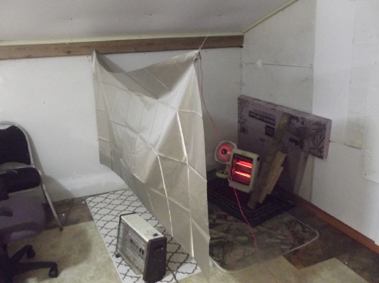
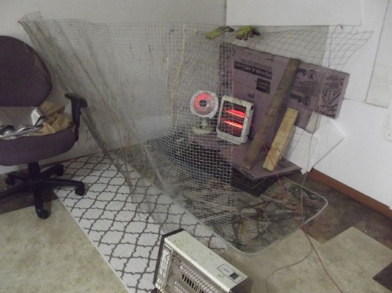 Another problem was that the cloth
blocked the heat. So I took it down and threw up a piece of
'hardware cloth' mesh. Should be just as good for 60 Hz.
Another problem was that the cloth
blocked the heat. So I took it down and threw up a piece of
'hardware cloth' mesh. Should be just as good for 60 Hz.
(BTW: The heater at the bottom of the picture is the one I
converted to 100/250 W, 36 V DC. If the batteries are charged I
use it and may turn off one or both of the others if it's not too
cold. But this winter has had a lot of freezing temperatures.)
But it seemed that there was electrosmog of some sort
still getting at me inside the cabin. There was that one
loud tone in my ear that didn't seem to diminish overnight. I was
sure tinnitus takes days to fade, but shouldn't it at least be
down a bit overnight? And again it's been worse in the winter.
Finally on Christmas eve I thought of the two windows
on the West wall - the bedroom window and one on the ground floor
not very far away. These were on the opposite side from the power
line, out of sight of it, so I had thought no voltage gradient
fields could come through them. And I couldn't imagine that there
were any sort of radio transmissions coming from that direction.
Starlink, all the way from space? Seems ludicrous. But I'm
probably wrong about the power line electric field, and the
magnetic field was probably another matter too. I stapled up an
alume window screen over the bedroom window and grounded it. It
seemed to help some overnight. So in the morning I put up 2 inch
mesh chicken wire on the downstairs window, and then the upstairs
because the window screen was too narrow for full coverage. Now
there's 2" chicken wire on ALL the windows. If it's the 60 Hz
power lines, that should work, but if some RF or UHF is coming
from God knows where, a much finer screen would be needed. [It was
an extension cord outside the windows - read on!]
There's still other electrosmog in the onion layers!
When it's quiet, at low volume, I have heard what sound for all
the world like CW transmissions (Morse Code) in my ears since
probably my early teens (late 1960's). Not high pitched - maybe
500 Hz to 2 or 3 KHz. Sometimes I there are two or three stations
at once. I hadn't noticed them for quite some time. But I think
it's just because they were drowned out by other, more powerful
tones. Now that I have been blocking so many sources of those,
peeling away layers of onion, I hear them again. I don't think
these ones are just irritation that builds up: I think they are
the actual CW transmissions, in real time, hitting my hearing
mechanism somewhere, somehow. And somehow they seem to penetrate
the grounded metal roof and walls of the "Faraday" cabin. (When AM
radio stations used to broadcast at very high powers, some people
are known to have heard them "in their fillings", including what
was being said and the music playing.)
I know most of the Morse code letters, but I've never
trained on reading it. They're low volume and by the time I've
figured out what one letter is, three or four more letters have
passed. Unfortunately I can't take them from my head and record
them or feed them into a computer. My best guess is LF (~500 KHz)
marine radio weather forecasts. I sailed on weathership Vancouver
once and in the radio room all the sounds coming in over the
radios were "deja vu" (well, deja ecoute.) When I was in the coast
guard in the later 1970's the forecasts were sent by hand on a
schedule, but last I remember seeing, they were typed in and sent
automaticly. (And they're mostly read by computers and turned into
text automaticly, too.) They may be always on. I only hear them
when all else is very quiet. I heard them as a kid in Edmonton far
from the coast, so I think the skip carries them far and wide. In
fact, that's why they're broadcast at such low frequencies - to
reach to ships far out at sea. Dang! Now I'm hearing two! There's
the one in my right ear that prompted me to write this section,
and now another lower pitched one in my left ear. Naturally these
can be even more annoying than the continuous tones. If they were
at the higher volume of those, they might be unbearable. ([26th] -
OMG, I think I just caught a "CQ CQ" (-.-. --.-
-.-. --.-) going by in my left ear while I was typing
the paragraph below this one. That means "broadcasting to all
stations", typicly starting a marine weather report. Then a "V"
(...-) after, probably starting "VAK" or VAG" or whatever -
Canadian coast guard radio station identifiers. But I can't follow
the rest. A few minutes later: Now the higher pitched one has
started up again in my right ear.)
Surely this whole system is redundant now with the
ubiquitous, planet-wide satellite communications?
[26th] At last I seem to have finally figured out the biggest
cause. From the entry is a 150 foot extension cord (120 V
AC) to the travel trailer that for some reason I still have. It
has a heater with a timer and in cool to cold weather I go out
daily and put it on for an hour so it doesn't get damp and mouldy
inside. The cord goes outside right at the door, but it runs along
the base of the wall of the cabin. Some signal might be getting in
under the metal wall. And then it goes across the lawn, passing
outside the bedroom window. Hmm, that must explain what's been
coming in the window, since there's nothing else on that side but
forest. I thought the cord was too far away to matter. Apparently
not! [But it was one of two things, along with the WiFi hub.]
I didn't expect that it would have much effect
inside, but I unplugged it Christmas evening and finally felt like
I wasn't being "hit" with something very notable during the night.
Perhaps I had the cord unplugged over the summer and so it was
better then. I have been reluctant to unplug it because about
every second time I plug it back in, the ground fault breaker
trips and I have to go to the house and reset it.
[30th] I still feel there's some irritation - probably lesser but
still there - preventing the ringing from subsiding more
overnight. Another layer in the onion. I think it's still the
heaters, even at the far end of the room and with two grounded
shields between them and the bed. There just doesn't seem to be
anything else. But I couldn't be in the cabin without the heaters.
I thought "How can I reduce their AC magnetic field?"
If they were DC it wouldn't matter, and the heaters could run on
DC as well as AC. But if one converts 120 V AC to DC, after
filtering (with really big capacitors) it would be near 171 volts,
which would burn out the heaters. So one would have to transform
the voltage down by the square root of two first. For heaters that
would be a big ugly transformer or a x10's KHz PWM converter,
either of which would doubtless make plenty of its own noise.
+171 V to -171 V = 342
V peak to peak = 120 V RMS. The rectified waveform is +171 V
peak to 0 V, still 120 V RMS
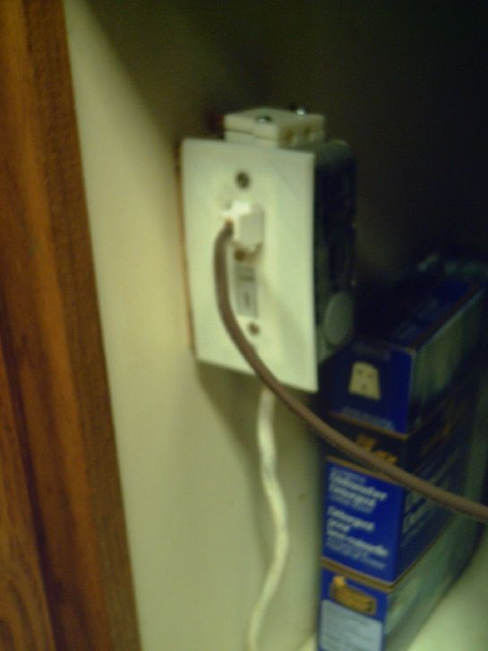
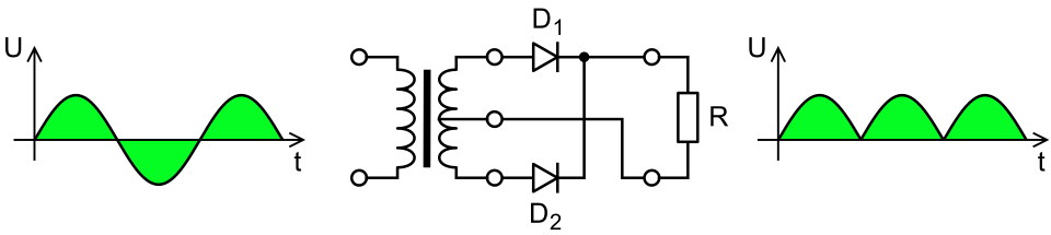 But I could rectify it
and not filter it. (No transformer, 4 diode rectifier
bridge.) That would reduce the peak-to-peak travel of the AC waves
from 342 volts to 171. That should make some reduction in
the oscillation of the magnetic fields.
But I could rectify it
and not filter it. (No transformer, 4 diode rectifier
bridge.) That would reduce the peak-to-peak travel of the AC waves
from 342 volts to 171. That should make some reduction in
the oscillation of the magnetic fields.
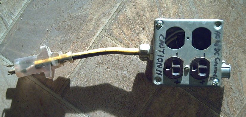 So I took one of my new bridge rectifiers and a
scrap outlet box and made a box to do that. Hopefully it will
help. (The rectifier can barely be seen through the spare holes.)
So I took one of my new bridge rectifiers and a
scrap outlet box and made a box to do that. Hopefully it will
help. (The rectifier can barely be seen through the spare holes.)
At first I plugged the two heaters into this box.
Then I realized the field still was in the extension cord. So I
put the box at the far end of the cabin, so the entire extension
cord, heaters and all were unfiltered DC instead of AC.
Then, in addition to the two layers of wire screen
between the heaters and the bed, I put a conductive fitted sheet
under the mattress liner and grounded it. (3 of the 6 DC outlets
in the bedroom - in the already shielded cabin - are now occupied
just for shield grounding wires!) Since the heaters are on the
floor and the power cords run below bedroom floor level, that too
should block out much of their magnetic and electric field from
lying in bed. I think I've finally reduced and blocked out most of
the AC power noise and getting more relief by morning. But then I
have to get up and walk across the unshielded yard to the
electricly noisy house, and start my day. And maybe drive into
town on the highway right under the power lines. Can I ever get
away from it long enough for the ringing to fade away entirely,
even once?
-----
Dr. Gerard Hyland, Biophysics, University of Warwick, 2
times Nobel Prize contender Medicine, says:
“A major contemporary threat to the health of Society is
man-made ‘electrosmog’. This non-ionising electromagnetic
pollution of technological origin is particularly insidious, in
that it escapes detection by the senses – a circumstance that,
in general, tends to promote a rather cavalier attitude,
particularly with respect to the necessity of ensuring an
adequate degree of personal protection. Yet the nature of the
pollution is such that there is literally nowhere to hide.”
At the serious risk of being repetitious I think electrosmog
of all sorts is going to be one of the major health preoccupations
of this century. So far we are just making it worse and worse,
adding layer upon layer to the onion. AC power lines were the
start 100 years ago. Then radio. Now UHF - "microwaves". Some are
saying putting WiFi in schools is a crime because of the radiation
it exposes developing children to. Warnings by those in the field
about health problems that 5G would bring were disregarded and it
was rolled out everywhere anyway without a pause. ("Follow the
Science!" - unless it's not convenient.) Some vandalism of 5G cell
towers may be because of people being driven nuts by them being
too close to their dwelling place and finding no way to get
relief. I'm glad I moved to the country but sorry my place is so
close to the highway power line. So far my [known] adverse
reactions to all this have mostly been tinnitus. (That is, since I
got the cell phone out of my pocket. After a year or two it was
making my leg 'pulsate', a 'muscle tic' under the pocket where I
kept it. At first I would think it was the phone vibrating, but it
almost never was. What would have been next, cancer?) Others have
trouble sleeping, more serious health problems or even die of
cancer, especially brain cancer from cell phones too often and too
long held up to the ear - or even kept under the pillow. As Hyland
says, our senses don't detect anything - until it has manifested
itself as some health problem whose cause is usually 'unknown'.
ESD
(Eccentric Silliness Department - No electrostatic
discharge)
* I wanted to sit in the dark. So when I turned off the last
light, I was delighted.
* 'sno boots like snow boots when there's snow. (Where did all
that snow come from, anyway? It's like winter when it's
actually... oh ya!)
"in
depth reports" for each project are below. I hope they may be
useful to anyone who wants to get into a similar project, to glean
ideas for how something might be done, as well as things that
might have been tried, or just thought of and not tried... and
even of how not to do something - why it didn't work or proved
impractical. Sometimes they set out inventive thoughts almost as
they occur - and are the actual organization and elaboration in
writing of those thoughts. They are thus partly a diary and are
not extensively proof-read for literary perfection, consistency,
completeness and elimination of duplications before publication. I
hope they may add to the body of wisdom for other researchers and
developers to help them find more productive paths and avoid
potential pitfalls and dead ends.
Electric
Transport (No
Reports)
Other
"Green" & Electric Equipment Projects
A New Tech !
Resistance Heater made With Power Diodes
(advantages over resistance wire)
[16th] The 60 power diode bridges arrived. With 26 of them (two
diode drops each), they will start turning on at Vf 0.7
* 52 = 36.4 volts. Below that voltage they should draw no current
from the supply, protecting the batteries from overdischarge.
Another possible advantage is that electric
resistance heaters tend to dry out the air. Possibly the solid
state heater with no red-hot element won't have that effect? But
I'm guessing.
36.4 volts is only about 11 or 12% battery remaining.
But they only pass about 200 mA per diode at .75 volts, which is
only: 2 diodes * .2 A * 39 V = 16 W. And that is just under
50% charge. It will take a very long time to deplete even one KWH
at 16 watts, and the depletion will drop as the voltage does.
Presumably during the day much more than that will be made by the
solar panels, even in December fairly far north.
However, the highest diode drop we will see is about
.8 volts, which is only about 1.3 amps. 2 * 1.3 A * 41.6 V = 108
watts. That's a pretty small heater, and only at 100% charge with
very low line drop to the heater. We'd need several banks of such
heaters. Instead, we will probably choose instead to have a few
fewer diodes and assume the small energy loss as the voltage drops
will be made up by solar power within a day.
I got two 5" x 5" heatsinks for a diode based heater,
and a 6" x 7" x .375" slab of alume for a hotplate 'burner' from
my stashes. I arranged the bridges on them. These are thick enough
to thread a #10-24 bolt mounting hole for each bridge without
putting a bolt plus nut on each one.
Later I decided to spread the diodes on the hotplate
out a little, so I found a little bigger burner plate, 7" x 7.5" x
.375". (Both pieces scraps from AGO courtesy of Jim Harrington
some years ago.) I thought of setting up a little g-code program
and having the drill router drill the mounting holes in 'perfect'
rows. But I'm not sure about having a high speed router drill the
alume, so I decided to do it by hand. Mark. centerpunch. drill.
tap. 'Tap' (cut bolt threads) is by hand anyway. with the threader
tap in the battery electric drill, loose enough to slip rather
than snap. It's much faster for smaller threadings.
[17th] We can make tables:
Heater characteristics with 26 Rectifiers
Diode
Drop (V)
|
Battery Voltage
(drop *52)
|
Current (A*2)
|
Power (W)
|
Battery %
|
.70 or less
|
36.4 or less
|
0
|
0
|
12
|
.75
|
39.0
|
0.400
|
15.6
|
50
|
.80
|
41.6
|
2.600
|
108 - The voltage will
rarely be this high
|
100
|
.85
|
44.2
|
10.40
|
The voltage will never
be this high!
|
|
.90
|
|
20.80
|
|
|
While it would be nice to have all
current stop at 26.4 volts, it looks like the heater power
available would be too low.
We could have 25-1/2 rectifiers using only one pair of diodes in
the 26th one, but I'll skip that table.
With 25 rectifiers
Diode
Drop (V)
|
Battery Voltage
(drop *50)
|
Current (A)
|
Power (W)
|
Battery %
Charge
|
.70
|
35 or less
|
0
|
0
|
0
|
.75
|
37.5
|
0.400
|
15
|
~12
|
.80
|
40
|
2.600
|
104
|
88
|
.85
|
42.5
|
10.40
|
416 - The voltage will
never be this high! |
>100
|
.90
|
|
20.80
|
|
|
Well Dang, that still looks kind of low powered. Drop one more
rectifier?
With 24 rectifiers
Diode Drop (V)
|
Battery Voltage
(drop *50)
|
Current (A)
|
Power (W)
|
Battery %
Charge
|
.70
|
33.6 or less
|
0
|
0
|
0 - cells
minimum
allowed
voltage
|
.75
|
36.0
|
0.400
|
14.4
|
~10
|
.80
|
38.4
|
2.600
|
100
|
20
|
.85
|
40.8
|
10.40
|
424
|
100
|
.90
|
43.2
|
20.80
|
The voltage will never
be this high!
|
|
Now the voltage minimums are looking pretty low. 38.4 V is only
20% charge. I don't think I want it still running 100 watts there
- the idea is to stop making heat before the battery is too low
while (LED) lights and other light loads can still run until the
sun comes back.
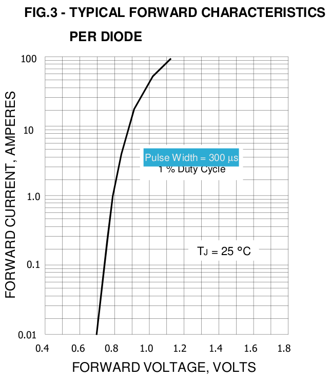 [Later, replacing the original speculative
paragraph... When I actually made the heater and tested it, there
was a major factor not even mentioned in the datasheet. That is
that the forward voltage drops are given only for 25° C. Nothing
was said about temperature factors, leaving one to assume they
worked the same regardless of temperature. In fact, the forward
voltage drop of the rectifiers is much lower at 100° than at 25,
so the power consumption goes up drasticly with temperature!
Current listed for .9 volts is reached at .6 volts when the heater
is somewhere around 100° and continues to rise with temperature.]
[Later, replacing the original speculative
paragraph... When I actually made the heater and tested it, there
was a major factor not even mentioned in the datasheet. That is
that the forward voltage drops are given only for 25° C. Nothing
was said about temperature factors, leaving one to assume they
worked the same regardless of temperature. In fact, the forward
voltage drop of the rectifiers is much lower at 100° than at 25,
so the power consumption goes up drasticly with temperature!
Current listed for .9 volts is reached at .6 volts when the heater
is somewhere around 100° and continues to rise with temperature.]
I think I want to try 25 bridges (50 pairs of diodes)
and see what happens. Also of note: 400 W / 25 bridges = 16 watts
per bridge. They can certainly handle that!
I drilled & tapped the holes in one of the
heatsinks, then mounted the components, which were 12 diode
bridges (13 on the other one) and a high temperature cutout
switch, 120° C. The vacant diagonally opposite corner spaces with
holes will be for mounting the heatsinks on some frame to be the
body of the heater. That took the evening and made for a somewhat
late bedtime.
It does occur to me that the voltage/power gradients
could be achieved, and be more carefully tuned, using a
microcontroller and ordinary resistance wire. But that would
require pulse width modulation to turn down the heat, and
switching that heavy load would make substantial electrosmog. I
doubt I'd want it in my Faraday Cabin.
Another approach could be multiple resistance wire
elements of differing wattages, again preferably with an
'intelligent' control. (eg, 40, 80, 160 & 320 watts, providing
40 to 560 watts in 40 watt steps.) That wouldn't use PWM.
But I want to try the "dumb" diode approach and see
how it works. There may be more advantages than are apparent in
advance, and it's an easy experiment (no programming to do) that
shouldn't take long. (unless of course it is a success. That would
warrant further development!)
I connected the diode bridges together with bare #14
solid wire. That avoided a lot of wire stripping and pushing
stranded wire through little holes. Only the overtemperature
switch got insulated wire, the wires being longer and running past
other terminals. I put it on the power supply. What, nothing? Oh,
wait... the terminal marked "+" is the cathode... that's "-" if
it's a load rather than a power supply, not "+". The other way
around it worked. It started drawing current somewhere around
17-18 volts, but the 12 bridges needed 22.5 volts to draw 2 amps
of current. I'm not so sure 25 bridges - 50 diodes - will make
much heat with "only" 40 or so volts. But I didn't test it long
enough to get very warm.
Later I wired up the other heatsink with 13 bridges,
allowing 50 or 51 diode drops.
[21st?] I connected them and put in a
switch. (High-OFF-Low, 50-OFF-51) I tried it out at the 36V outlet
in the kitchen.
Both house and cabin batteries were rather low owing to the little
solar power available in December (and still trying to run what
little heat it could in the cabin). On "high" it took a long time
to ramp up to a high power. Then I switched it to "low" and it
began ramping down again - presumably it was saving the battery,
and had the voltage been much lower, "high" wouldn't have ramped
up to higher powers either.
 [23rd] I remembered that I had a
backup power supply in the cabin system to keep the battery from
getting overly depleted. It had been unused and unplugged but was
still installed. I plugged it in and turned it up so it would
charge the battery. Then I could use the battery at night to run a
36 volt heater for extra heat (besides the 1300 watts from two 120
VAC heaters at the far end of the room).
[23rd] I remembered that I had a
backup power supply in the cabin system to keep the battery from
getting overly depleted. It had been unused and unplugged but was
still installed. I plugged it in and turned it up so it would
charge the battery. Then I could use the battery at night to run a
36 volt heater for extra heat (besides the 1300 watts from two 120
VAC heaters at the far end of the room).
So the battery voltage was a volt or more higher, and
the heater was much stronger. In a relatively short time it ramped
up to 21 amps, 720 watts. Just when I thought the 20 amp breaker
would blow, the thermal switch shut it off. A few minutes later it
came on and did the same thing again. It was probably averaging
400-500 watts. [Later estimate: 300-350 W] Not huge but definitely
a heater. In an hour the room was up from 13° to 16 and rising.
With a laser temperature sensor the highest temperature I measured
was 113°C, directly on a rectifier metal package.
I flipped the switch to add in the 51st diode, 25-1/2
rectifier bridges, into the circuit. It got less dicey, starting
near 7 amps, 315 watts and running up to just under 16 amps, 590
watts, and then shutting off. But it didn't stay off very long. (A
couple of minutes? I didn't time it.) It was probably putting out
about the same amount of heat overall - on longer, off shorter. I
suppose if the heat switch didn't open, on the higher setting the
breaker would blow before the diodes got too hot. I'm not so sure
on the "lower power" setting.
[24th] I ran the heater overnight in the bedroom in the cabin. It
raised the temperature from what would have been around 14 or 15°
to 19 or 20. Much nicer! (-2 to -4 outside. +1 in the uninsulated
part of the building.) It used something over 3 KWH. By spring
that energy will probably be available from the sun, but in
December it just adds to the huge electrical consumption from the
power grid, much of which this winter is for the cabin bedroom
heat. If I had any financial sense I'd abandon the cabin until the
weather improves. I'm still burning lots of firewood in the house
anyway. I certainly hope to finish the cabin insulation next
summer! And maybe get the woodstove in.
 I used a piece of alume siding as a
mounting for the heater. I cut some "Z clips" (meant for mounting
solar panels) in half. I attached the heatsinks by the open corner
positions to the siding. The switch handle is on the back. I was
hoping for heat transfer through the "Z" clips to the big piece. I
used some heatsink paste on the "Z" clips (only at the plate, not
at the heatsinks - oops), but it didn't seem to transfer very
well. I got the idea to put more clips under all the corners by
inserting them under the bridges in the occupied corners. That
would strengthen the mountings, but mainly it should help transfer
more heat to the "back" piece.
I used a piece of alume siding as a
mounting for the heater. I cut some "Z clips" (meant for mounting
solar panels) in half. I attached the heatsinks by the open corner
positions to the siding. The switch handle is on the back. I was
hoping for heat transfer through the "Z" clips to the big piece. I
used some heatsink paste on the "Z" clips (only at the plate, not
at the heatsinks - oops), but it didn't seem to transfer very
well. I got the idea to put more clips under all the corners by
inserting them under the bridges in the occupied corners. That
would strengthen the mountings, but mainly it should help transfer
more heat to the "back" piece.
It's certainly easier to carry put together into one
piece with the switch attached and the power wire clamped on with
cable ties!
[25th] The plate didn't get very warm. I put the
Z-clip "legs" at all four corners of both heatsinks by putting
some under the bridges and this time I managed to put heatsink
grease at every join. The plate got warmer, but by no means
burning hot. And even on "low" it ran until around 680 watts,
drawing 18 amps at about 38 volts. On high it hit about 800 watts,
21 amps, but didn't blow the 20 amp DC circuit breaker. The
accumulating kilowatt-hours on the monitor told me it was getting
most of its juice from the power grid via the backup power supply,
not through the clouds and snow on the solar panels.
In freezing weather it's just a supplement to the
1300 watts of 120 volt heaters. In "shoulder" weather I can unplug
those.
Hopefully I'll get the ceiling in and the rest of the
cabin insulated next summer. Then the bedroom won't need so much
heat! ...and get the woodstove in, too!
[January 1st] I cut a shallow arc out of the
bottom of the plate so that only the cooler outside edges touch
the floor and cooling air can flow under the warmer middle area.
I note that the heater seems to get warmer on "low",
with 51 diodes, than on "high" with 50. It heats up more slowly,
so the whole body gets warmer before the heat switch hits 120° and
shuts it off.
It could use thicker heatsink mountings that
would carry off more heat to the backplate.
I confess that seeing how the power and temperature
have something of a positive "runaway" feedback loop, I'm a bit
leery of the mechanical overtemperature switch, which cuts in and
out every few minutes. It should probably have a second thermal
"trip" switch at a slightly higher temperature. If that has to be
repeatedly reset manually it means the regular switch has fused
closed and needs to be replaced. If it became fused "on" and was
plugged into a 20 amp outlet the breaker would probably blow
before it got too hot, but not if it was a bigger breaker. Or, a
20 (25?) amp fuse in the unit itself might substitute for the
thermal trip switch. If it keeps going it will surely exceed the
maximum temperature of the diodes and a bridge will go poof.
Open Loop Air Heat Pumping (OLAHP)
Indoor-Outdoor Air Heat Exchangers
[26th] I watched a new video by the guy from Belarus (what was
that YT channel again?) about indoor-outdoor air heat exchangers
(or HRV's or whatever they call them). He said that claims of 90+%
efficiency from exchangers made with criss-cross corrugated
plastic sheets ("coroplast") aren't real. They are measured under
ideal conditions in indoor test setups with zero wind and at the
lowest possible air flows. He said really they are closer to 50%
in actual use. Aha! I had always been surprised by the high
efficiency claims when plastic is such a poor heat conductor, but
had no basis for doubting them. He was getting higher actual
efficiencies with his own DIY units and was trying to do better.
In this video he was making his own corrugations from aluminum.
Since effectiveness of the exchanger is paramount to
getting high coefficients of performance (COP's) in the OLAHP
system, I watch his videos. But because the air being cooled in
OLAHP is compressed, I can't just copy his or other designs.
I had long thought that the design of heat pump
radiator coils would be excellent except that they are made to
exchange just one temperature difference - heated gas to room air,
the same two temperatures across the whole unit. For the
indoor-outdoor exchanger a linear range is needed. Where the
outdoor air first comes in, the compressed air going out has
expended most of its heat and warms the incoming air a bit. At the
indoor end, the incoming air is ideally almost up to room
temperature, while the outgoing compressed air is still just a
little above room temperature. Along the length, the compressed
air slowly cools as it warms the incoming air around it. In the
middle, the compressed air is (just over) half way between room
temperature and outdoors while the incoming air has been warmed to
(almost) that same temperature.
I looked at the radiator I had on the wall. It seemed
impossible with all the convoluted, multi-shaped extremely fine
fins on very small pipes to change it. They were made to wrap
around the centrifugal fan whose small diameter but very long
"squirrel cage" or "hamster wheel" blades ran from one end of the
pipes to the other. But this time I looked more closely. The
complex shape was composed of several sets of simple rectangular
fins each with eight pipes going back and forth. To get the
complex shape, the fins of the individual rectangles were
interleaved between each other or just touching each other. Only
the end plates tying them together were actually the complex
shape. That meant they could be separated into rectangular
sections.
One might then unsolder the caps on the ends of the
pipes and re-route them so the eight pipes were in parallel
instead of in series. (Plastic tubes, hose clamped on, could carry
the compressed air across to the next length. Or solder on new
copper pipe pieces.) That way if the compressed air inside was
cooling (say) from the left to right, and the outdoor air in the
duct was warming as it traveled right to left, there could be a
gradual temperature differential along the whole length of the
unit. But again they were made for the fan to blow the air across
them, not to have air flowing along their length. But to get this
flow direction, one might have these finned radiator pipes inside
a rectangular duct and place baffles in the duct to force the air
to flow across, back and forth between the two sides of the pipes.
This sounded workable.
The fins on the commercial radiators were incredibly
fine, not much thicker than alume foil and just a millimeter
apart. Further, they had little slits and bumps to roughen them
and make sure no air got by without transferring its heat. One
suspects they were probably even pure aluminum rather than a less
heat conductive alume alloy. And while not soldered, they were
crimped well onto the copper pipes as evidenced by little indent
rings in the copper pipes every millimeter and the fact the the
whole finned length looked like alume with no copper showing. (The
14 copper pipes of the ones I ended up using were 21 mm apart in
two staggered rows, ensuring that no part of any fin was more than
6 mm from a pipe, and even that distance was between two or three
pipes.)
Given something to push or pull the air through, a
much smaller unit would surely exchange heat much better than the
big box with large finned elements that I made earlier and have
been using. And the simple way to pull the exact right amount of
air through would be to have the warmed air outlet connect
straight to the air compressor input. Otherwise the compressor
would probably have an easier time pulling air through cracks
around windows and doors, and the heat exchanger air might be
little used. (So much for the idea of just drawing room air and
thus having the exchanger supply fresh but warmed air to the
room!)
My big box seemed to be at best maybe around 70% efficient
when running the smallest compressor with the lowest air flow,
resulting in the COP's I vaguely measured as just 3 to 4 with a
100 watt compressor giving 300 or 400 watts of heat, which COP
dropped lower and lower the bigger the compressor was. A heat
exchanger that captured 80+% of the outgoing heat with somewhat
higher air flows with a somewhat bigger compressor might make it
COP 5 or 6 and actually make the room warm down to freezing
weather.
Of course the pivoting vane compressor that I have
yet to get working should add a couple more (COP 6 to 8?). And a
pivoting vane 'compressed air engine' to assist the compressor by
using the cold compressed air before sending it outside well below
outdoor temperature, should raise it some more. COP 10 or more at
0°C outdoors, 20° inside, is still the "ultimate" goal!
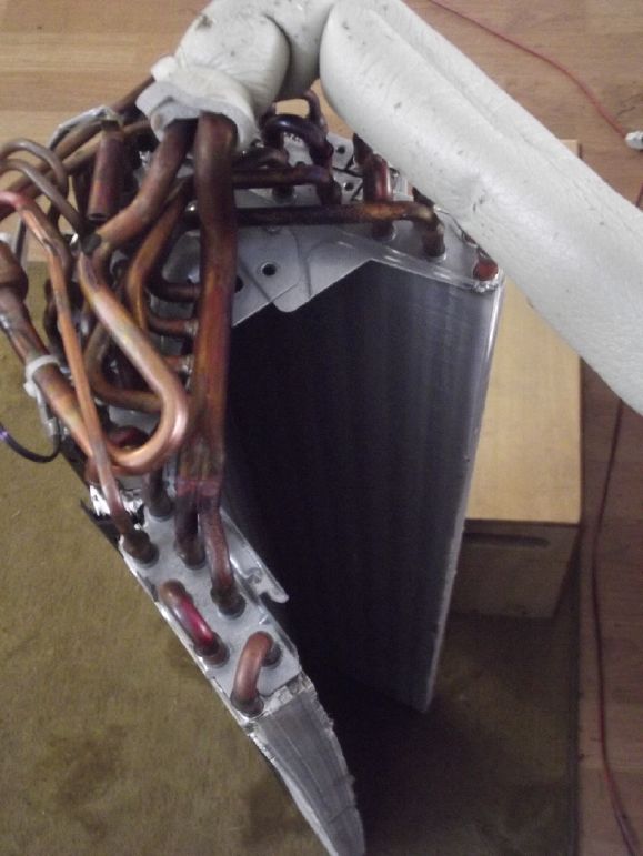 [27th] I decided it would be worth making and
trying a new heat exchanger, to try out even with the fridge
compressor. I had a second commercial heat pump radiator unit,
stored away, collected when I was at "heat pump" Perry's and he
was disposing of spare parts clutter. I fetched it and
disassembled it.
[27th] I decided it would be worth making and
trying a new heat exchanger, to try out even with the fridge
compressor. I had a second commercial heat pump radiator unit,
stored away, collected when I was at "heat pump" Perry's and he
was disposing of spare parts clutter. I fetched it and
disassembled it.
This one had two 1" thick by 6" wide radiator
sections each with 14 pipes as well as three smaller sections with
8, 4 and 4 pipes. They were about 33 inches long without the end
piping. These seemed so substantial I decided to just use the two
big ones. I cut the radiator pipe units apart. The pipes all
connected at one end in various ways and looped around at the
other.
I didn't look forward to unsoldering all those pipe
ends - silver solder no doubt - and reconnecting the 56 bent ends
with solder to end up with 14 pipes all in parallel and then
recombined at each end. Luckily I got the idea to simply cut the
ends right off. The "alume foil" fins weren't soldered to the
pipes, so it should be possible to pull a few off the ends until
there was some pipe sticking out. Straight, clean pipe. It was
still going to be a job, but now not so impossible looking. And it
can be sloped a bit so moisture will drain to the cold end of the
pipes.
I sized things out. The width was the length of the
fins plus an inch of insulation above and below: 6 + 1 + 1 = 8
inches. The height, with one set "folded" in front of the other
rather than having a long thin box, was the width of the fins (1")
with 3/4 of an inch air space on each side, plus an inch of
insulation in front, behind and in between: 1 + 3/4 + 1 + 3/4 + 1
+ 3/4 + 1 + 3/4 + 1 = 8 inches. (Add an inch for sloping the
pipes: 9 inches.) The length of the pipes was about 33 inches. Add
pipe connection spaces and room for pieces and insulation: say 38
inches. That's way smaller than my present heat exchanger box and
with the air being pulled sideways, back and forth in sections
through those finely spaced fins, it will probably be much more
efficient - perhaps even the proverbial 90% misleadingly claimed
for the criss-crossed coroplast units. With the direct connection
of the passively warmed air duct to the compressor intake I'm
hoping for a COP of 5 or 6 - 500 or 600 watts worth of room
heating from a 100 watt fridge compressor at zero° outdoors. And
to be able to use a larger compressor for more heating still with
similar COP.
[28th, 29th] I Pulled fins off one end of one unit
to expose the pipe ends. I found a short piece of pipe that fit
over the radiator pipe ends if it was reamed out just a bit on the
inside.
I pulled fins off the other three ends to expose all the pipe
ends. I found a 7mm socket that would press just a bit on the
outside of the pipes. Placed in a drill and spun it shrank them
slightly and cleaned off the outsides of 1/4 inch length at the
end of each pipe. I cleaned out the insides with a step drill that
seemed about right. And then the short piece of pipe fit perfectly
over them just as it was. All I needed was to find a much longer
piece the same to make all the joiners from. I thought cleaning
the inside of the ends of pipe for soldering would be a nuisance -
then I remembered that HCl ("muriatic") acid cleans copper nicely.
Assuming I had more of that size pipe, the one remaining challenge
seemed to be how to make some sort of manifold to combine the 14
pipes into 1 larger pipe at each end of the unit.
I couldn't find any more pipe of that diameter. In
all the reams of copper pipe I had, there was plenty with the same
outside diameter, but no more with the slightly thicker wall that
made it that exact inside diameter. I decided to use the other. It
would just take a lot of solder to fill the gaps.
[30th] I made a wooden form and bent 14 pipes
around it for the center join between radiator sections.
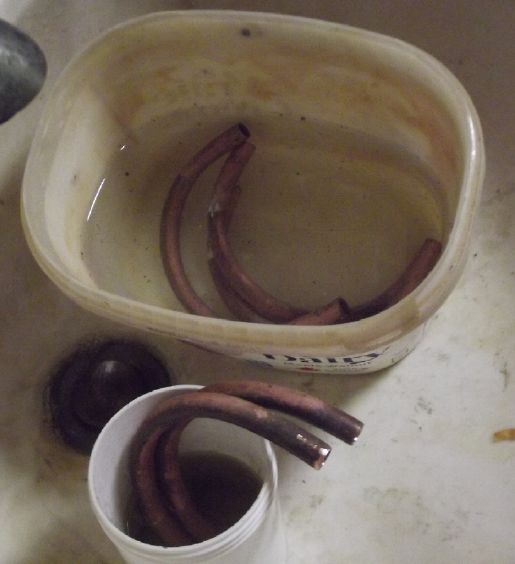 Then I cleaned the ends of the pipes in
hydrochloric acid, which turned green with copper chloride from
the copper oxide. (then rinsed them off.)
Then I cleaned the ends of the pipes in
hydrochloric acid, which turned green with copper chloride from
the copper oxide. (then rinsed them off.)
"Faraday
Cabin"
Construction
Having moved the stairs
in November, at some point I cut the upper landing shorter. I also
angled the end 30° to leave it more "roomy" below. I didn't finish
the railing until the 26th and didn't take any pictures before
that.
Upstairs Light Switch
[3rd] Having moved the stairs and reversed the door, I spent the
day moving the upstairs light switch to the other side of the
door. Most of it didn't go smoothly. I put a weight on a string
and shoved it through a hole into an empty stud space to fall down
to the hole for the old switch so I could pull the light's wire
through. It absolutely refused to fall! It seemed to defy gravity.
And I couldn't pull it out, either. (Maybe it somehow got caught
behind the very wire I wanted to move?) I tried and tried.
Eventually I went and got a copper wire and twisted a "needle eye"
into the end, around the string. I pushed it in until it pushed
the string and weight past whatever was in its way. The final
insult was when I tried to screw the cover on the switch. It was a
bum electrical box - one of the holes wasn't threaded and the last
screw wouldn't go in! I got a threading tap and fixed the box. By
this time the day was done.
I still have to fill the old switch hole. But both
ceiling lights are working again - main entry and the room
upstairs.
[4th] I finished tiling the bathroom floor and roughed in the sink
and composting toilet.
The sink sat on a (free!) kitchen cabinet. I cut out
the top and back to accommodate the sink, and also screwed a 2 by
board along the wall to support the back end of the sink. I
couldn't find the fittings I needed to connect the drain in my
plumbing scraps.
Here's a $itty subject I'd rather not write about. I
will anyway. The composting toilet will be an enclosed bench with
a seat hole. The front will open to insert a 5 gallon bucket. It
needs a ventilation stack. I have long had the theory that the
closer to the source the ventilation is, the less is needed. I
have thought that toilets should have an air vent hole just under
the seat, connected to an outdoor vent pipe. A very small fan then
would suck air from under the seat. (Maybe pressure activated when
someone sits down?) Very little air would be needed and the smell
would never even get up into the room.
There are many and various composting toilets. (try
youtube) With many, one has a drain for the urine that goes
outside to a sump or wherever. For a single guy, peeing mostly
elsewhere allows using a simple bucket for the excrement. With
most types, some organic matter such as leaves, sawdust or grass
clippings is collected and placed near the seat. After going, a
handful or scoop of this is dumped into the bucket to cover the
$it.
In lieu of a fan, my idea is that warmer air rises,
and around here the dwelling is almost invariably warmer than the
outdoors. So a pipe going outside from under the bench, turning
and going up outside the wall, will draw air to the outdoors.
Maybe black plastic pipe to help keep the air heated. (at least if
it's sunny.) The more directly it can draw air, the smaller the
vent can be.
Instead of flushing into a septic tank, I want to use
waste, well buried and not for root crops, as fertilizer. Our farm
soils are getting poorer and poorer in various trace minerals and
the nutritional value of our food has been dropping gradually but
continually for 75 years or more. We are more and more acquiring
nutrient deficiency diseases such as arthritis (see "in passing")
and others. Everything ends up in the environment somehow,
somewhere, but until we see dung as a farming resource and not as
trash to be disposed of, this is almost bound to continue getting
worse. Using a composting toilet and then burying the product
under fruit trees, berry bushes and next year's garden seems to me
to be about the simplest way for rural individuals to make good
use of it and grow better gardens. I'll leave town solutions,
individual or group, to others.
[8th] I cut the plywood sides so that the bucket was almost flush
with the underside of the bench, just a 1/8th inch gap. Then I cut
a hole almost at the top of a bucket. A black ABS pipe goes
directly into this vent and out a hole I cut in the wall.
Hopefully the odor will be confined to the bucket and go right
outside, and no fan will be needed. If it is it hopefully will
only be needed when the unit is being used.
Having a hole saw that size, I went with a 1-1/2"
pipe from the bucket through the wall
[9th] After buying a 1-1/2" 90° elbow, I used it, an adapter and a
2" by 5' pipe going up. (pieces I happened to have - the up pipe
should be longer both to pull air better and to end way above nose
level.) I also bought pieces for the sink drain.
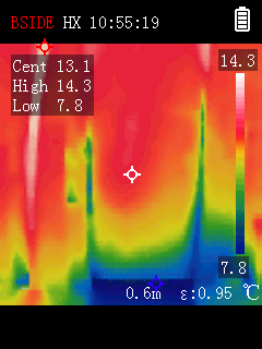 [11th] The thermal imaging camera I had ordered
arrived. It was freezing outside. I checked around the cabin. In
the heated bedroom upstairs there was as expected heat loss
through the window and through the big cracks under and around the
door. The door wasn't supposed to be an "exterior" door!
[11th] The thermal imaging camera I had ordered
arrived. It was freezing outside. I checked around the cabin. In
the heated bedroom upstairs there was as expected heat loss
through the window and through the big cracks under and around the
door. The door wasn't supposed to be an "exterior" door!

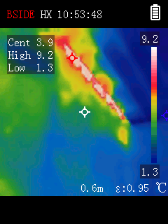 Checking the inside wall to the rest of the cabin
yielded a big surprise. Right at the ceiling heat was pouring
right through - across the dividing rafter or just under it. The
whole ceiling was supposed to be well insulated - I don't know
where or how I left a gap! (Note: At this time the bedroom itself
wasn't much warmer than the indicated 9.2 warmest degrees.)
Luckily(?) I didn't see a similar stripe of heat going through to
the outside of the roof.
Checking the inside wall to the rest of the cabin
yielded a big surprise. Right at the ceiling heat was pouring
right through - across the dividing rafter or just under it. The
whole ceiling was supposed to be well insulated - I don't know
where or how I left a gap! (Note: At this time the bedroom itself
wasn't much warmer than the indicated 9.2 warmest degrees.)
Luckily(?) I didn't see a similar stripe of heat going through to
the outside of the roof.
This wouldn't be fixed when the cabin was finished,
either. The heat would be going right into the (planned) unheated
attic space. Without the camera I might or might not have
suspected the finished cabin was harder to heat than it should
have been, but I'd never have guessed where the heat was going! It
will probably be similar on the other side of the peak. Now that I
know about it, it will be easily fixed with a few slabs of styrene
foam on the attic space side.
Just from this the 150$ I spent on the camera will
soon enough be recouped in firewood and electricity saved or more
comfort!
[16th] The culprit was a narrow gap between the ceiling and the
top of the sloped wall frame. Notwithstanding that I had put up
trim in front of it in the bedroom, lots of air seemed to be
getting through. After all it was the warmest part of the room
above the heaters, going into the unheated space. I stuffed
polyethylene foam into the crack from the bedroom. This helped
considerably. The room was notably warmer in freezing weather
around zero to plus 3°. I should stuff in some more from the other
side.
First I wanted to use gap filler foam. To my surprise
I had a can. I could hear liquid when I shook it, but it didn't
work. Everything was stiff and the plastic trigger broke off. None
came out. There was a date code: "best before January 2017." I
didn't know canned foam had expiry dates! Also I'd have sworn I
used up all the old cans when I did the cabin's outside gaps and
then garage door. The other cans still worked then (a couple not
too well by the time of the door). I had even bought a couple of
new cans having missed the last one (I hope) on the shelf. Oh
well. Where was I? The polyethylene foam was better for this than
styrene foam because it would compress down a bit. It could be
stuffed in and counted on not to have an air gap above or below.
Washroom Receptacle with Switch for Light
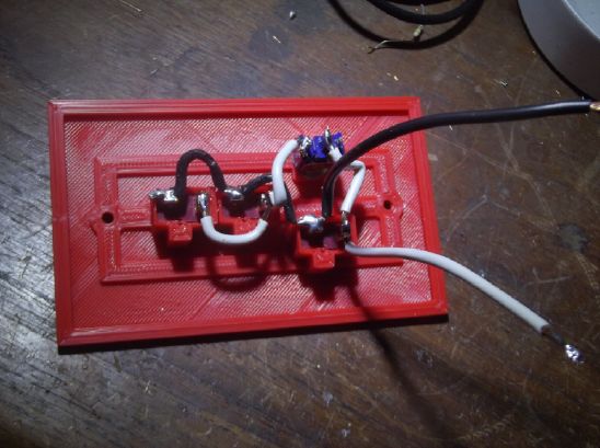 [?] I had been noticing that some of my PLA
printed items had been deteriorating and pieces had broken off
some of them. I decided to use ABS instead if it would print well.
[?] I had been noticing that some of my PLA
printed items had been deteriorating and pieces had broken off
some of them. I decided to use ABS instead if it would print well.
I 3D printed an ABS triple receptacle wall plate with
a small switch for a light or other light load. I had red ABS
loaded in the printer, so I used it. It printed nicely. The
dimensions for PLA didn't work with ABS. The T-sockets wouldn't go
into their holes. I reworked the dimensions for those slightly
larger and tried again. They fit very tightly, which is good. I
didn't bother melting some plastic or putting in tiny screws to
secure them - I was pretty sure they wouldn't push out. The astute
observer will notice that the white pigtail connection is on the
wrong side. The lower two outlets were switched instead of the top
one.
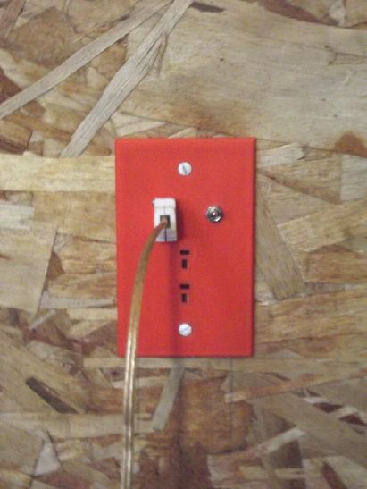 [23rd] The wire was run and the electrical box put
in in the washroom area before the wall panel and the floor. I now
installed the receptacle, connected another 20 amp breaker and
tried it. Then I took it out and fixed the "+" connection pigtail.
Sigh!
[23rd] The wire was run and the electrical box put
in in the washroom area before the wall panel and the floor. I now
installed the receptacle, connected another 20 amp breaker and
tried it. Then I took it out and fixed the "+" connection pigtail.
Sigh!
Later I wondered which was really the most durable 3D
printer filament. I looked on line and came up with
"polycarbonate", "PC". It was also the highest temperature, with
the extruder to be set to around 265° C. That made it better than
nylon for printing electrical sockets! I ordered a couple of
spools. Then I started reading about it being finicky to print. I
guess I'll find out!
I hadn't finished putting up the railing around the
upstairs landing after I moved the stairs. I wouldn't want to
stumble over the edge! I finally got most of that done, having cut
some of the pieces on previous days. I had cut the landing shorter
and at a 30 degree angle sometime previously, since most of it was
way past the door now. Shorter and especially the angle made it
more open in the room below.
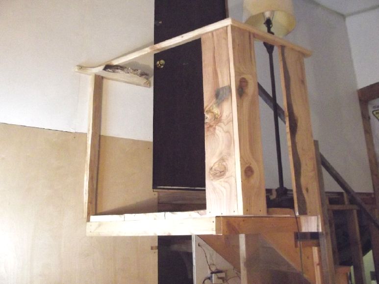 [26th] I finally finished the railing. (Nothing
more is painted of course.) The vertical post at the wall ended up
between two wall studs. How to attach? I changed the plan a bit
and cut a special shelf piece that screwed to the stud on each
side and held the top of the post in place. It has a "live edge" -
the outside of the tree.
[26th] I finally finished the railing. (Nothing
more is painted of course.) The vertical post at the wall ended up
between two wall studs. How to attach? I changed the plan a bit
and cut a special shelf piece that screwed to the stud on each
side and held the top of the post in place. It has a "live edge" -
the outside of the tree.
Often I have both hands full. I wanted a small shelf
anyway so I can set something down to open or close the door -
coming and going.
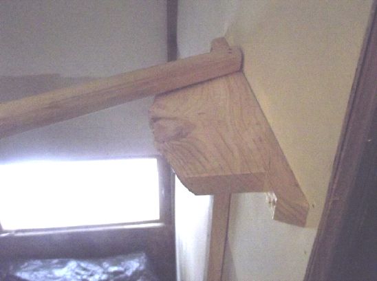 The
shelf.
The
shelf.
Haida Gwaii Gardening
(No Report)
[3rd] The cell did hold its voltage,
around 1.3 volts. I did a 10 minute load test at only 1000 ohms -
a load on the order of a milliamp. Then it was down below 1 volt.
No charge to speak of. (200 microamp-hours?) Through the day
occasionally I tried alternately shorting and recharging the cell.
The currents did seem to go up, substantially. And down. And up...
It still needs more than an order of magnitude more current to be
useful for much.
[4th] I added water until dirty water came back out the slot as I
added more. About 6 cc. (Total presumably 16.) It helped. Max.
momentary short circuit current went to 102 mA. Then I thought of
the idea of gold plated metal instead of graphite. My experiences
with gold plating so far have been poor. But I had a sliver of
actual gold metal. I dug it out and inserted into the slot as a
terminal piece (one of three slivers - two of graphite foil).
Short circuit current next time was 137 mA. A load test ran 15
minutes instead of 10. This seemed to be getting somewhere, but it
certainly had a long way to go to be a useful battery. I don't
think using gold foil would increase capacity, only current drive
by reducing resistance. It did seem to do that.
[5th, 6th] I cycled the battery occasionally, drawing it down to
around .6 volts with a load and then recharging until it pretty
much stopped drawing current.
Nickel-Zinc (What?)
Frustrated with the low performance, I got the idea
to try nickel oxyhydroxide as a positive electrode again.
Previously I had taken that electrode from dead
nickel-metal hydride "D" cells. They had worked initially but the
material would swell and lose conductivity, so they would get
worse and worse. This time I had the cylindrical cell with the
graphite on the outside and the porous ABS basket to prevent the
material from pushing inwards. I could crunch up the material,
fill the space well, and hopefully it wouldn't be able to swell
much. If it didn't work, maybe I have to make the basket just
slightly larger in diameter and twist it into place against a
certain amount of pressure. And maybe make it stronger.
I do have a formula for making my own nickel
oxyhydroxide mix, from the Ovonics patent plus a trace of samarium
oxide oxygen overvoltage raiser to compensate for using a lower
pH, and now that I can crunch the substance into place in the
cell, I should be able to make it work. If I do ever produce
nickel-zinc cells I would do that, but I know for sure the dry
cell mix works. It's one less variable. (BTW, as explained quite
some time ago, Ni-MH dry cells seem to fade mainly because the
limited amount of water inside gradually dries out. Overcharging
accelerates this. The substances inside seem to be still good.)
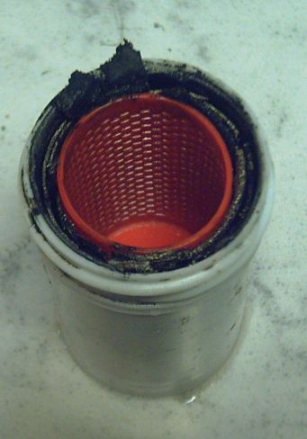 [7th] I made it. There was an opened "D" cell from
some other time, sitting in a 'tupperware' thingy. I unwrapped it
and put in thin, curved pieces, already almost the right height,
around the rim (the rim having a graphite gasket sheet as current
collector), then pushed the basket in. Then I stuffed in more
pieces wherever I could fit them. I think I got it packed pretty
tight.
[7th] I made it. There was an opened "D" cell from
some other time, sitting in a 'tupperware' thingy. I unwrapped it
and put in thin, curved pieces, already almost the right height,
around the rim (the rim having a graphite gasket sheet as current
collector), then pushed the basket in. Then I stuffed in more
pieces wherever I could fit them. I think I got it packed pretty
tight.
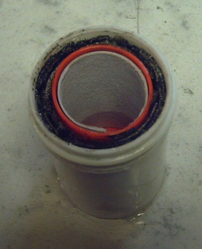 Then I trimmed off the material -
knife cut and scraped it to lower than the basket rim. I painted a
prepared sheet with osmium/acetaldehyde (one side only) and fitted
it into the basket.
Then I trimmed off the material -
knife cut and scraped it to lower than the basket rim. I painted a
prepared sheet with osmium/acetaldehyde (one side only) and fitted
it into the basket.
I put in 5 grams of zinc powder with a
trace of zircon.
I had noted that it was awkward without a
filler/inspection hole on the first cell. I took the new lid and
the first cell and drilled a 3/16" hole in each. I didn't glue the
new cap, either. I filled the cell with electrolyte. It's
supposedly 10% KCl, 5% Na2SO4 and 5% KOH. But much of the Na2SO4
seems to precipitate out and is on the bottom of the electrolyte
jar, so it might only be 1-3%. It took 25 cc to fill the new cell,
which said I hadn't filled the first one even half way. That might
be part of it's poor performance. I filled it up with water too.
It took more than I expected. (Oops, now it's probably too weak?)
Anyway, with the new holes I can "dip the tank" to see how full it
is and check the pH. The pH of both cells was about 13.
It occurred to me to use the gold leaf for this cell
too, but I didn't disturb it in the other one. That is just as
well. I wasn't thinking: at the higher voltage of nickel
oxyhydroxide, gold too would oxidize! (Gold oxide might make a
nice, high voltage electrode? a horrifying thought, given the
price of gold!)
Something else that occurred to me was that both
Ni-Cd and Ni-MH have pretty high self-discharge. something like
10% in the first 24 hours, then 10% in the next month, but
depending on temperature. They are supposed to be recharged at
least every 6 months. In a year without recharge they are pretty
much dead and corroding inside. Both cadmium and metal hydride are
about the same voltage, and both lower than zinc. Zinc holds its
charge in non-rechargeable dry cells for years. Also because the
self discharge is so similar in both nickel types, it must
(surely) be because of the nickel side. Nickel oxyhydroxide is
above the oxygen evolution voltage, so it's not surprising.
Earlier formulations wouldn't hold a charge above about 40° C, and
it wouldn't hold a charge in my cells until I raised the pH to
13.5 . If one used a good oxygen overvoltage raising additive
(like samarium oxide) the self discharge might be eliminated. Just
something to keep in mind for the future if I'm ever formulating
my own nickel 'trodes. (But I'd rather do cuprate ions or nickel
manganates.)
I shorted this cell too, since the "+" was probably
pretty much discharged and because the zinc needed to dissolve
some ions to recharge and start fusing the powder particles
together and to the copper wire.
After discharging it, I took the other cell off the
stand to test this new one. I charged it at 2.0 volts. Nickel-zinc
should be around NiOOH (+.5V) - Zn (-1.25V) = ~1.75V. Generally
they're rated as 1.6 volts. I ran a couple of discharge tests.
They seemed pretty weak but 10 times better than the other cell.
Voltage dropped substantially with state of charge, from around
1.7 to well under 1 volt after 20 minutes, still putting out good
current into the 100 ohm load. It should improve.
Well into a 100 ohm
discharge test; 1.35V, 13mA.
Wait... how to tell which cell is which?
Better label them!
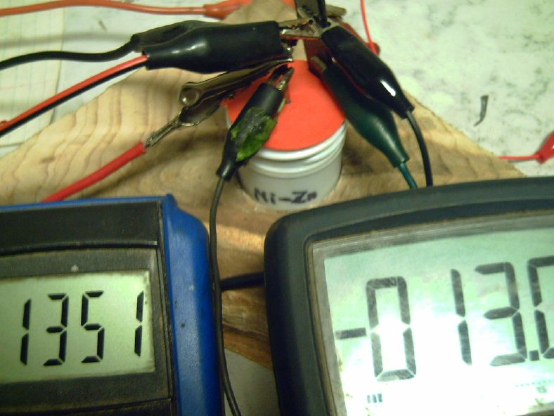 [8th] After
charging overnight, a morning load test seemed substantially
better. The improvement might have been more quantifiable if I had
written down the previous figures. I did record it this time. I
missed some readings by having breakfast, but it was definitely
still at a higher voltage after 30 minutes.
[8th] After
charging overnight, a morning load test seemed substantially
better. The improvement might have been more quantifiable if I had
written down the previous figures. I did record it this time. I
missed some readings by having breakfast, but it was definitely
still at a higher voltage after 30 minutes.
[9th] When it was charging, and after hours on charge, current
seemed to go up a bit instead of down, eg, from 8 mA to 12. I had
the thought that the nickel mix was formulated for pH 14, and
nickel oxyhydroxide's voltage is near the upper limit of what
works in water. The voltage goes up a bit with dropping pH.
Perhaps at pH 13 it needed an oxygen overvoltage raising additive
like samarium oxide? That would mean making my own nickel
hydroxide mix after all. The other thing I could try would be to
raise the pH. I opened the cell's lid (WHY did I glue the first
one?) and found the zinc had been bubbling slightly - perhaps
hydrogen in compensation for the nickel side self-discharging,
bubbling oxygen as it charged. (or, didn't charge!) I added 1 gram
of KOH.
After a while I checked. pH was maybe 13.5 . The
voltage while charging seemed to have gone up a little higher,
over 1.9 volts. Charge was 13 mA. I decided I should discharge it
for the sake of the zinc, so I ran a load test. It wasn't
dissimilar to the previous.
Charge current didn't want to drop under 10.0 mA. But
it wasn't rising. A load test some hours later ran substantially
longer with the voltage still in the 1.6+ volt range. Things are
looking up! Time to double the load, with 50 ohms instead of 100?
[10th] I did do the extra load. It still ran for an hour at over
1.3 volts, delivering almost 30 mA-H. In fact, above 1.59 volts
for 15 minutes, then it dropped more quickly through 1.59 to 1.4
volts (20 minutes), then started dropping very slowly, hitting
1.28 after another 25 minutes. With all the energy in the 1.3 volt
range, I can't help but think there must be some considerable
amount of manganese in the nickel mix. That might make it more
like the Sanyo mix than the Ovonics. I also think it still has
more balancing to do between the zinc and the initially discharged
nickel hydroxide.
time - volts, milliamps
0 - 1.839 V, turned load ON
1 - 1.692, 34.2
5 - 1.646, 31.5
10 - 1.615, 30.9
15 - 1.589, 30.5
20 - 1.547, 29.6
25 - 1.488, 28.5
30 - 1.428, 27.4
35 - 1.390, 26.6
40 - 1.362, 26.0
45 - 1.339, 25.6
50 - 1.319, 25.2
55 - 1.229, 24.8
60 - 1.280, 24.5 load OFF
61 - 1.614 charge ON
62 - 1.841, 39.0 mA (charge current)
I probably should have run it down to 1.0 volts,
where it would probably be out of energy and dropping pretty fast,
but by an hour I was getting very tired with watching it. I'll
probably run another partial discharge to compare. Hopefully
there'll be further improvement. Then I'll increase the load
again. There seemed to be no improvement on the next run, probably
because I stopped it too soon. So I stopped recording numbers and
let it run down to ~.66 volts, in ~105 minutes.
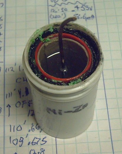 I opened the cell to check the
progress of the zinc.
I opened the cell to check the
progress of the zinc.
Note the bits of loose green nickel
hydroxide at the top of
the outer electrode. Unless they make electrical connection
with the rest, they'll stay inert & green. They may have
been
nickel metal foil "current collector" paths that have oxidized
(and expanded) in the lower pH of this cell.
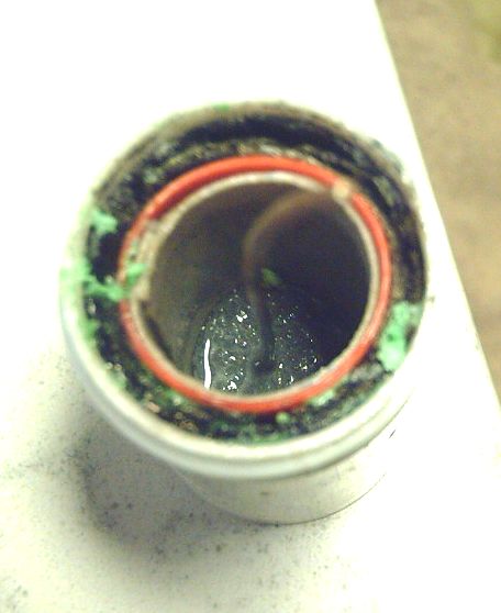 I couldn't see much so I drained out the free
liquid. There seemed to be a fine plating of zinc on the copper
wire. I scratched at the zinc on the bottom. The powder was
slightly clumping together, but I could easily dig down to the
bottom. So it seemed most of the zinc had never been discharged to
zincate and back again, which should have glued the zinc particles
together pretty well.
I couldn't see much so I drained out the free
liquid. There seemed to be a fine plating of zinc on the copper
wire. I scratched at the zinc on the bottom. The powder was
slightly clumping together, but I could easily dig down to the
bottom. So it seemed most of the zinc had never been discharged to
zincate and back again, which should have glued the zinc particles
together pretty well.
That would be because most of the nickel
hydroxide had never been charged to oxyhydroxide - the "+" and the
"-" states of charge were wildly out of balance.
I didn't notice any white zinc oxide powder. The free
liquid would contain most of any zincate there might be, so I
poured it carefully back into the zinc basket, none around the
outside. And put the lid back on.
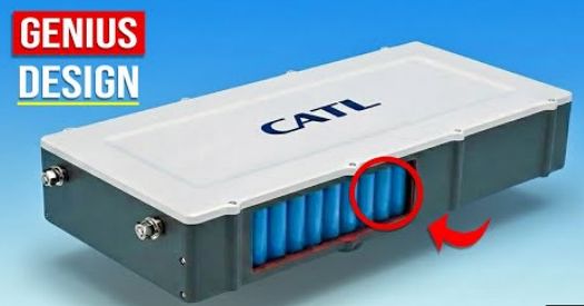
BTW...
If my test cells seem patheticly small compared to what's
needed for mass storage or EV's,
remember they must have thin electrodes with much interface
surface area between them,
and then look the cells these big and presently much hyped
CATL batteries are made of.
I'm thinking my cells might be produced narrow diameter as
now, but say 200mm (8 inches)
tall, 15 or 20 amp-hours each for large batteries.
Gold Plating, Nickel-Manganese Oxides Blah Blah
Chemistry is one thing, but the new cell design is
working wonders. It's solved various problems I've had with making
batteries that actually work according to plan. Finally I can
concentrate on what goes into the cell without having problems
with the mechanics.
So, presently I am (at long last) testing a cell with
"typical" nickel oxyhydroxide with "everlasting" zinc. I've
finally discovered that "typical" mixes known to work in dry cells
(at pH 14) need to be kept at pH 13.5+ rather than the ~13 I've
been working at. It's a chemie that just a few more tests on the
present cell should (hopefully) prove that an enterprise could
start producing useful, long lasting batteries as soon as
production processes can be set up, even if all other research
should fail or cause delays until they are made practical. Just in
case some such opportunity should arise and nothing else is proven
yet.
I started thinking about the nickel manganates combo
again, perhaps averaging out at about NiMn2O4.
In case I can't get the organicly chelated copper electrodes to
work well, this should be a good, and presumably much simpler to
make, alternative.
Nickel (NiOOH) has too high a voltage to use gold or
gold plating - it seems only graphite will work, and it's less
conductive. Nickel-manganese oxides should (I believe) react at
the lower voltage of manganese dioxide (MnO2), but be
rechargeable. The spinel crystal structure should be conductive at
any state of oxidation (where Mn2O3/MnOOH is an insulator, so it
won't recharge).
The trouble with plating any metal to protect it is
that if there is the slightest gap in the plating anywhere, the
metal will corrode away. And there are always stress points, and
metals expand and contract - differently - with temperature, so
even if "perfect", minute gaps may eventually appear in platings.
Nickel plating gaps seem to have killed many supposedly long life
nickel-XXX alkaline batteries, especially large flooded cells.
Solid nickel might be employed but it only works at pH 14. Gold
costs too much to use the solid metal.
Now, it seems to me to be the surface of graphite
that is less conductive, the junction between the electrode
substance and the graphite. What about gold plating graphite to
reduce (if not eliminate) that contact resistance? Exposed
graphite wouldn't corrode, so small gaps in the plating would have
little effect. The plating could even be too thin to see, and only
the contact side of the graphite need be plated. A gram of gold
could plate oodles of battery cell graphites!
My latest idea of the chemie of nickel manganates is
that as the electrode reduces, like NiOOH to NIOHOH, hydrogens
would enter the molecular structure, making for example,
NiMnMnOOOO into NiMnMnOOOOH. This process could carry further,
possibly even to NiMnMnOHOHOHOH, which would be moving four
electrons per molecule. More likely somewhere in between, moving
two or three. (And likewise, each hydrogen taken turns a water
molecule into an OH- ion to oxidize the zinc to zincate, Zn(OH)4--
.)
[11th] All this charging and discharging was to gradually "even
up" the 'trodes, because one (the zinc) was starting totally
charged and the other (the nickel hydroxide or the copper
substance) probably totally discharged. There were things that
could be done about this before filling the cell.
One way would be to discharge the zinc to potassium
zincate and pour this into the zinc basket as part of filling the
cell. Another would be to charge the nickel side to oxyhydroxide
with bleach. It would seem that doing one or the other of these
would save an awful lot of time and effort.
I had a bottle of sodium hydroxide-zincate. I sucked
out a cc of electrolyte with the syringe and squirted in one of
the zincate. The trouble is I don't know what the concentration of
the zincate solution is. It doesn't say on the bottle. Just
something to try!
I looked for how to make zincate on line. Best answer
seemed to be on the subject of "plating aluminum", for which a
plating of zincate is first used:
" We always made our own zincate. It's just
zinc oxide stirred into a concentrated sodium hydroxide
solution.
"It's been a million years, but the only test was via
hydrometer. I don't remember the value we were shooting for, but
it reminded me of a loose pancake batter. We almost never
checked it when we were in production. You could tell when it
was getting weak. The zincate coating looked thin/bad."
Pancake batter?? (Could he mean pancake syrup?) Well,
surely I can use KOH instead of NaOH. But I still need to figure
out the amount of zinc element I'm putting into the cell, and then
how much KOH is already in the solution from this. I have a
feeling that it's way too much KOH (pancake batter??) for the
amount of zincate. I would guess zinc oxide in the cell doesn't
convert back to zincate because the KOH isn't concentrated enough.
Instead (if able to form) ZnO builds up and clogs things up.
Hmm... I have ZnO. If I want 5 grams of zinc: Zn+O:
65.4+16=81.4 . 81.4/65.4*5g=6.22 grams of zinc oxide. Then I need
to measure the KOH as I add it so I know how much of that it took
to dissolve all the oxide. I think It'll be way more total KOH
than is supposed to go into the cell, to make the right amount of
zincate. How can the KOH be diluted without diluting the Zn(OH)4--
?
Maybe I can add some zincate, which will also
be the total KOH component of the electrolyte, and some Zn metal
powder. And then try bleaching the nickel compound. If that's what
I'm using in the "plus" side.
[12th] After overnight it was still charging at 20+ mA in the
morning. The fluid was down a bit and I added about another cc of
zincate. This increased the charging to about 29 mA.
Without waiting for the rate to drop, I ran a load
test/discharge with 25 ohms. It lasted exactly 3 hours from 1.668
volts/55.8 milliamps at the 1 minute mark dropping to .598
volts/22.1 milliamps at the 180 minute mark. I
calculated/estimated 127.5 mA-H of current. I'll definitely have
to increase the load again to reduce the time spent if I'm to
chart the progress manually again! It charged at over 40 mA for
quite a while.
Current per Area of Interface
If I short the Ni-Zn cell, current starts momentarily
at around 600-700 mA, drops quickly below 500 and is soon down to
300. How much interface cross section is there? The paper
perimeter of the zinc basket is about 22 mm diameter. The height
of the perforated section in the zinc basket is 42 mm. Then the
perforations probably block about 50% of the area. We get:
22*pi*42*.5=14.5 square centimeters. That's not much so it
explains the low currents. Maximum current per square centimeter
is 700 mA / 14.5 sq.cm = 48 mA/sq.cm . 300 mA makes it just 21
mA/sq.cm . These figures aren't very high. The best cells achieve
up to 200. We are handicapped by
(a) Needing a rigid wall between 'trodes. The zinc needs to be
loose with room to spread out, but the other electrode has to be
held out of its space. Hence the perforated basket, cutting the
available cross section in half.
(b) the thick separator paper. In higher current cells the papers
are very thin.
(c) the treatments of the separator paper.
But these are the things that were done to make the zinc
"everlasting"!
(d) [belatedly measuring...] The "+" electrode cylinder "wall" is
over 3 mm thick. That's just how it worked out with the pipes I
found and the 1 oz. ointment jar. Their diameters worked out
together for my test cells. Such a thick 'trode is bound to have
lower rates. High rate positive 'trodes are generally under a
millimeter thick, even .5 mm.
How can things be improved?
1. Make the cylinder of "+" material thinner. If it works out with
the present equipment I could put two (three?) layers of .5 mm
graphite sheet around the outside of the jar. Okay, the copper
pipe still fits inside two layers. Not three. I could use three if
I'm stuffing in dry cell nickel strips instead of compacting
powder with the pipe. (And after all I have several layers of the
nickel fitted in where in the dry cell they were one layer with
both sides exposed to the metal hydride electrode.)
2. The most obvious way to add interface cross section is to make
the cells taller. 8 inches (~200mm) would multiply the currents by
about five, ie, 3.5 amps dropping to 1.5 instead of .7 to .3 .
That would still be "not much" for such a size, but more useful.
(It would also be almost problematic to load such a tall tube with
"+" material by hand. Maybe a machine would do it as a flat sheet
on plastic and then roll it into a tube and glue the seam and put
a bottom on it? But I'm getting way ahead of myself.)
3. They could be made wider. Doubling the width would double the
interface and the storage capacity. But there would be more wasted
space filled with water in the center. The zinc or zincate only
needs a little of the space in the basket as it is. (It might
actually be better to make the cells narrower and leave less empty
water in the middle. I might do that if I was to find pipe that's
a little narrower than the ointment jars for tall cells.)
3. Multiple electrodes stacked in a single cell. But this gets
back into all the various designs that didn't work well for me.
The single cylinder with inside/outside 'trodes is the simplest.
It works. Still, one might consider a tack of rectangular zinc
baskets (reinforced at points so the centers can't bulge inward)
with thin pressed nickel (or whatever) ones sandwiched between
them. The nickel ones would be actually two, one facing each
direction with a graphite sheet in the middle. Internal graphite
connections do cause complications however.
4. Maybe better just to make small capacity simple tubes and
connect lots of them together. But they could all be thin-wall
tubes with bottoms and tops ending in recesses in one big square
tub, with interconnections on top, out of the individual cells.
Then a 'fake' top on top to hide all those connections. (Oh
wait... 3D printed bottoms would probably leak. They'd have to be
molded. Back to individual tubes, just stacked in a box.)
[13th] In the morning charging current was still 35 mA. Voltages
seemed to be down and currents up the more it ran. When the charge
was removed, the cell immediately dropped well below 1.8 volts. I
switched to a load test/discharge. I used 25 ohms again because
the voltage drop with heavier loads seemed too much. Even 25 ohms
makes significant voltage drop. Probably owing mostly to the thick
electrode it just couldn't handle higher currents - a working but
very slow cell. Even at 57 mA the voltage was quickly just under
1.6, where on the 12th it had been over 1.6 V for the first 15
minutes. But in just a few minutes the voltage drop was down to
about 3 mV/minute, where the previous day it had been more than
double that. That said it was likely to run for six hours rather
than three. Very promising!
I "dipped the tank" with a pH paper and discovered
the fluid was again down a bit. The long, long initial charge was
still using up water. pH still looked like about 13-1/2. At about
the 20 minute mark I added 1 cc of zincate solution. Filling
brought the voltage up by maybe 20 mV (to 1.590). It was now the
same as the previous test at that mark, and dropping more slowly.
By the 30 minute mark, the drop per minute was around 1.5 mV
instead of 3 or 4, still delivering over 55 mA. At the 60 minute
mark it was still delivering 1.524 volts. (Previous test: 1.374.)
At the 100 minute mark: 1.470 V/ 52.2 mA. (Previous
test: 1.192 V, 41.3 mA) ...and dropping by just over 1 mV/minute.
I talk off and on about making & programming some
microcontroller to record discharge tests automaticly, and even
shut them off at a low voltage, but somehow after all these years
I'm still writing the figures down by hand. I certainly can't
stick around for 6+ hours - I have things to do. OTOH, each hour
brings less change with the cell running so long.
It actually ran for nine full hours. It was still
.737 volts and dropping at just 2 or 3 mV/minute. I just didn't
want to wait any longer for it to drop to .6 before shutting it
off. Adding up the average current of each 30 minute section: 57,
55, 53, 52,51, and in the five hours I was away, estimating
roughly: 50, 48, 46, 44, 42, 40, 37, 34, 32, and then back again:
31, 30, 29, 27 mA. Adding these up and dividing by 2 (since they
were 1/2 hour periods): exactly 500 mA-hours. Wow, half an
amp-hour! But there must be around 4 amp-hours or more of material
in each 'trode. I don't think it's reached its capacity by any
means.
[14th] Morning charging current was still over 50 mA, at just
1.725 volts. 13 hours at 50 mA would be 650 mA/hours. Really, that
hadn't done much more than recharge what it put out yesterday.
Given that capacity has been increasing with cycling, that would
explain why the voltage was low and the current high: it simply
wasn't near full charge yet. Maybe the next full charge will be
nearer to two amp-hours? Given the low current drive, charging and
testing this cell is now going to take days rather than hours.
I want a faster cell!
Ni-Zn Ointment Jar Cell #2
It seemed the best way to make another cell was to go
do it. I already had an extra basket & lid 3D printed and more
separator papers already toluened and SDBS'ed. And some more dry
cell nickel slabs/wafers/slivers. I already had the three layers
of .5 mm graphite gasket in the ointment jar. I put the stainless
steel pipe in the jar and fitted pieces of the nickel stuff in
around it. I could only get one layer of the .85 mm thick
electrode bits top to bottom, but managed to squeeze in a second
layer not full length nearer the top. It was probably only an
amp-hour or so of material. Then I pulled out the pipe.
This time I mixed 30 cc of water and 10 cc of bleach.
I poured the bleach into the cell jar and filled it. After a few
minutes I poured it out and filled the jar with water to dilute
out the bleach. Presumably now the positive electrode is at least
partly pre-charged.
I inserted the basket, working it down inside the
nickel stuff. Then I painted the paper on one side (inside) with
the acetaldehyde & osmium powder mix. I rolled it up and put
it in the basket.
I cut a piece #14 copper wire for the minus current
collector and put 5 grams of zinc powder (with a bit of zircon)
into the basket.
I closed the lid, stabbed the edge slot with a piece
of thick sheet metal, and stuck a piece of graphite foil in to
connect with the graphite gasket as a "+" terminal.
I added about 22 cc of the electrolyte and a gram of
potassium hydroxide powder.
So, it was really pretty similar to the first Ni-Zn
cell, except that the nickel oxyhydroxide electrode was much
thinner and it was precharged.
The difference in performance was considerable. It
didn't do much right at first but with just a bit of discharge and
charge I started seeing momentary currents over 350 mA short
circuit and 250 to start the recharge. Continuing currents rapidly
rose with a bit of discharging and charging, first done in
seconds, then minutes.
I think, if the nickel was even partly charged, then
the reason it didn't immediately behave like a fairly charged cell
was probably because I used zinc powder, just dumped into the
basket. A little in the middle would touch the wire, but the
particles probably mostly didn't connect with each other. With
discharging connected zinc would turn to zincate and with
recharging it would plate on anywhere, gradually connecting the
powder particles. The thing to try for more immediate performance
would be (in addition to the bleach) to start with the 5 grams of
zinc already plated onto the wire as any blob. I guess the zircon
powder just gets dumped in. How it mixes with the zinc or zincate
I'm not sure. It's not soluble.
[15th] The cell started behaving much like the previous one except
with higher charging currents.
[16th] But then it seemed to be deteriorating. Test runs got
worse. It kept losing water. Finally I realized that the water was
frothy - the nickel hydroxide side seemed to be making bubbles.
Why? I had added a gram of KOH. I added another one. That seemed
to cure it. I guess the pH was still a bit too low.
[17th] In the morning there were still bubbles but the water level
didn't seem to be down. A load test was better. Something had
changed in my 25 ohm load and all the alligator clips connecting
it. Initial load went from 57.x mA to 63.x mA (at around 1.65V).
It's actually closer to what it should be - 1.65 V / 25 ohms = 66
mA. Beats me where the bad connection was.
In the test the voltages of course started out a
little lower. But they dropped more slowly and the test lasted
longer - in fact 145 minutes. It stayed above 1.4 volts 50% longer
and delivered around 90 mA-H.. After it dropped from 1.08 to .96
over some minutes, the predictable decline, suddenly it "rallied"
back to 1.082, stayed there a couple of minutes, and then started
dropping again, running maybe an extra 10 minutes. All I can think
is that some disconnected bit of zinc made contact and started
contributing. It makes me all the more want to try plating the
zinc onto the copper wire in advance instead of just dumping in
zinc powder. But how would I mix in the zirconium silicate? Maybe
by stirring the bath so the insoluble zircon circulates around and
hopefully gets caught in the zinc as it plates?
From the description of "making zincate" that
it's like "loose pancake batter" (...pancake batter??), I could
imagine the zircon being more or less suspended in place through
charging and discharging, rather than sinking to the bottom with
the first discharge.
In the evening I tried a brief test with the 25 ohm
load. It was obvious in 3 minutes that it was better than ever:
initially higher voltage driving higher current, and more
importantly, notably lower voltage drop per minute apparent even
in that short time. I look forward to a great test in the morning
if charging overnight doesn't somehow upset it again.
Someone sent me an email about a company making
lithium ion batteries using a silver-graphite powder mix as the
minus side current collector to eliminate lithium dendrites. The
idea was probably that the mix was more conductive than lithium,
so the ions would plate onto the mix rather than onto itself,
which is where dendrites form. (OTOH lithium is pretty conductive
too. IIRC, being so light, it's more conductive than silver by
weight. That is, you'd need a bigger cross section of wire, but it
would weigh less than the thinner silver wire. It's also so
reactive no one would ever make lithium wire.)
The idea being born, I wondered if using a silver
wire - or more practicly, silver plating the copper wire - would
make any notable improvement in my cells. Silver is only 12% more
conductive than copper, but these people seemed to think it was
worth it. Maybe it has to do with silver being larger atoms?
[Later: Doubtless it's because silver doesn't oxidize below about
+.4 volts. It should work instead of graphite with lower voltage
"+" electrodes!]
So... gold plated graphite for the "+" and silver
plated for the "-"? And osmium doped separator sheets? I could
call it the "precious metals" battery (even if they would be just
.001% of the metal substance)!
[18th] The next test was indeed better than any previous for this
cell, running almost 3-1/2 hours including almost 2 with good
voltages, which delivered ~115 mA-H. Total mA-H was around 160.
Again that was running the cell down to .600 volts in order to
connect more of the zinc and better balance the electrodes.
Charging however seems pretty slow and I won't be running more
than one long test per day.
[20th] I didn't get a chance for another test until this evening.
I thought I would just run it a short time and compare to the
previous. Instead I disconnected it before I went to bed and then
continued the load test in the morning.
[21st] In the middle of the day my memory slipped. I forgot that
neither gold nor silver had a high enough oxidation voltage to use
with nickel oxyhydroxide electrodes. [Apparently I'm rong about
gold - it works; read on!] I took a hardened wafer of silver and
pounded it thinner along one edge. I cut that edge off with
tinsnips. Then I annealed it (ah, Much softer!) and pounded it
some more. I was surprised that where copper would form an oxide
layer when heated to glowing red to anneal it, the surface of the
silver seemed fine. The blemishes were where foreign material
(anvil rust) stuck on from the pounding. A bit of nylon scouring
pad made it totally shiny again. This made it surprisingly easy to
rework and rework "ad infinitum". I guess that's why it's called a
"noble metal". I cut off a "spear" of it suitable for a "+"
terminal post for the cell.
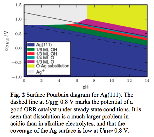 Jungner was said to have tested all
the metals and had found that only nickel would work. OTOH my cell
was pH 13.5 instead of 14. And had less concentrated electrolyte
with much less KOH. And I looked at a Pourbaix diagram of the Surface
of silver (right). I'm not sure of their purpose or exactly what
they were getting at (so I could have this rong), but it looks
like silver too forms a protective oxide layer in alkaline
environments. The article mentioned "Ag becomes
more stable relative to RHE as pH is increased. Hence the pH
dependent stability offers an explanation for the possible use
of Ag in alkaline fuel cell cathodes."
Jungner was said to have tested all
the metals and had found that only nickel would work. OTOH my cell
was pH 13.5 instead of 14. And had less concentrated electrolyte
with much less KOH. And I looked at a Pourbaix diagram of the Surface
of silver (right). I'm not sure of their purpose or exactly what
they were getting at (so I could have this rong), but it looks
like silver too forms a protective oxide layer in alkaline
environments. The article mentioned "Ag becomes
more stable relative to RHE as pH is increased. Hence the pH
dependent stability offers an explanation for the possible use
of Ag in alkaline fuel cell cathodes."
...or, then, in alkaline battery cell cathodes. Ag2O or AgO forms
a barrier layer that keeps the silver from corroding?!? Didn't
Jungner check "ALL" the metals?!?"
I just pulled out the terminal, a spear of graphite
foil, and stabbed in the silver one. Anyway, current went up until
I touched the aforementioned alligator clip.
By the time the test was over I had times with
voltages and notes scrawled all over both sides of a page. Trying
to piece everything together it seems it ran about 4 hours,
delivering around 226 mA-H. Still not much but going the right
direction.
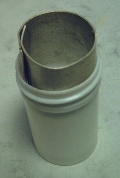 Next I'll be playing with higher loads and currents to see if the
silver terminal helps much. What would be even more helpful is if
the surface of the entire current collector was silver (if silver
continues to work). I went further with the rest of the silver
wafer, stretching it to ~100 mm on the rolling mill, annealing
whenever it got too stiff to roll further (twice). It's about .72
mm thick. I curled it around. It fits in the bottle but it's
rather short. The overlap could be sliced into and folded up for a
terminal without cutting it right off. If I anneal another wafer
and stretch it side to side first, I should be able to make it the
right height before making it long enough. Of course for any sort
of production one would want to silver plate a graphite surface
because silver in any quantity costs too much. It's okay to plate
over graphite because graphite won't degrade where there are any
gaps in the plating. Indeed it only needs to be plated on the side
contacting the active electrode. I would expect the plating to
much improve the surface conductivity to the active substance, and
hence current capacity.
Next I'll be playing with higher loads and currents to see if the
silver terminal helps much. What would be even more helpful is if
the surface of the entire current collector was silver (if silver
continues to work). I went further with the rest of the silver
wafer, stretching it to ~100 mm on the rolling mill, annealing
whenever it got too stiff to roll further (twice). It's about .72
mm thick. I curled it around. It fits in the bottle but it's
rather short. The overlap could be sliced into and folded up for a
terminal without cutting it right off. If I anneal another wafer
and stretch it side to side first, I should be able to make it the
right height before making it long enough. Of course for any sort
of production one would want to silver plate a graphite surface
because silver in any quantity costs too much. It's okay to plate
over graphite because graphite won't degrade where there are any
gaps in the plating. Indeed it only needs to be plated on the side
contacting the active electrode. I would expect the plating to
much improve the surface conductivity to the active substance, and
hence current capacity.
Ointment Jar Cell #3 - Silver current collector
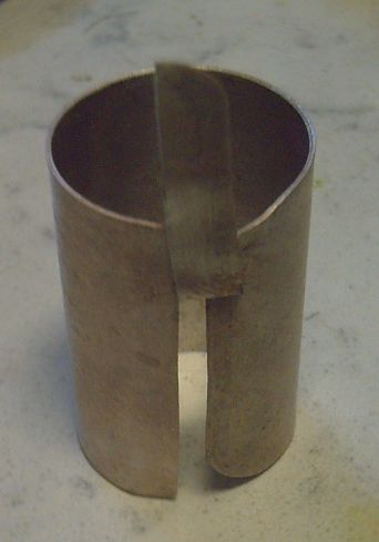 [22nd] I decided to try it. I took another 1 ozt
silver bar and annealed and shaped it in the rolling mill several
times, until it was the height and length for a cell. Again it
ended up right about .72 mm thick. I annealed it one more time so
it would roll up easily. Then I made the cut and folded one end
back on itself to make a terminal, and rolled it up to fit around
the rim of the bottle, but with one layer of graphite outside it
to take up space and make the active 'trode substance thinner. At
least this time, there should be no doubt that the terminal is
making 'perfect' connection to the current collector, since they
are one piece.
[22nd] I decided to try it. I took another 1 ozt
silver bar and annealed and shaped it in the rolling mill several
times, until it was the height and length for a cell. Again it
ended up right about .72 mm thick. I annealed it one more time so
it would roll up easily. Then I made the cut and folded one end
back on itself to make a terminal, and rolled it up to fit around
the rim of the bottle, but with one layer of graphite outside it
to take up space and make the active 'trode substance thinner. At
least this time, there should be no doubt that the terminal is
making 'perfect' connection to the current collector, since they
are one piece.
I [at first] decided on nickel (oxyhydroxide) again
because I'm more presently interested in comparing performance of
similar cells with other variables - here the current collector.
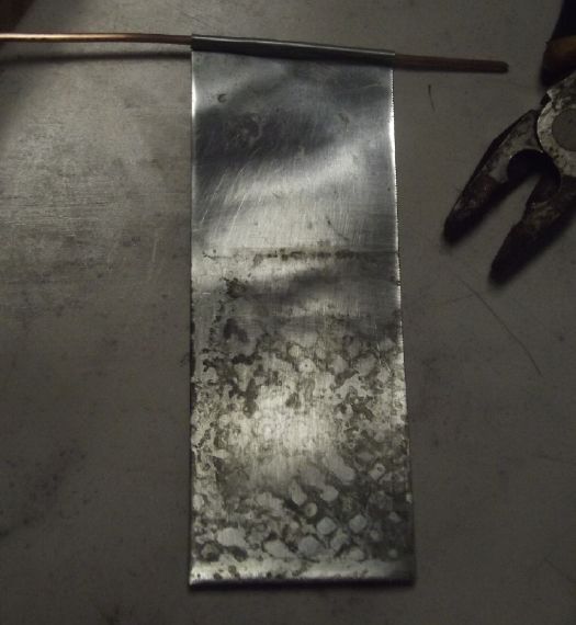 But I decided to plate zinc onto the
copper wire instead of just dumping some powder in to eventually
connect with enough charging and discharging. To speed things up,
I could wrap some thin sheet zinc around the wire, and then
electroplate enough to get it to bond. In the end I didn't even
plate it. I wrapped the sheet of zinc, slid it off the wire, and
crimped it down a bit so it didn't beck on slide easily. It seemed
to have a pretty good grip. (I did clean it.)
But I decided to plate zinc onto the
copper wire instead of just dumping some powder in to eventually
connect with enough charging and discharging. To speed things up,
I could wrap some thin sheet zinc around the wire, and then
electroplate enough to get it to bond. In the end I didn't even
plate it. I wrapped the sheet of zinc, slid it off the wire, and
crimped it down a bit so it didn't beck on slide easily. It seemed
to have a pretty good grip. (I did clean it.)
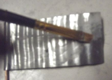 Then I unwrapped it, wetted a
paintbrush, dipped it in zirconium silicate powder, and painted
some onto the zinc, a thin layer. That's probably about the best I
can do at getting a uniform distribution of zircon when the zinc
isn't starting as powder.
Then I unwrapped it, wetted a
paintbrush, dipped it in zirconium silicate powder, and painted
some onto the zinc, a thin layer. That's probably about the best I
can do at getting a uniform distribution of zircon when the zinc
isn't starting as powder.
The new cell idea
with one-piece sheet silver current collector & terminal
(+)
and wrapped sheet zinc (-)
("+" substance TBA - probably organic/monel)
Meanwhile, Back at cell Ni-Zn #2
[23rd] I tested cell #2 again a couple of times, again just short
20 minute tests with a 15 ohm load. It didn't seem to be working
as well. I noted the water level was down and I added 3 or 4 cc.
That didn't seem to help much. The next test started worse yet. I
ended up fiddling with the silver "+" terminal. I finally stabbed
it in a little deeper. Voltage went up and results matched
previous days. So it would seem the silver terminal was losing
connection to the graphite sheet current collector. whether that
was purely mechanical or because the silver was oxidizing on the
surface remains to be seen.
The first Ni-Zn cell had (despite being placed at the
back of the counter) had got knocked over by test leeds and
spilled its liquid over the counter - KOH, KCl, Na2SO4 and
probably some zincate that dried into pale yellow zinc oxide. I
decided to take it apart and replace the graphite current
collector and terminal with the single sheet silver one, without
making a third new Ni-Zn cell - if I can get it apart intact. (Yay
I didn't glue it!) I can only deal with one cell at a time anyway.
At the same time I could do graphite sheet just as outside filler
and reduce the nickel active substance to one layer instead of
three for better performance - less than 1 mm thick instead of
over 2. Then see how the silver fares as a single piece current
collector + terminal.
And again at the same time I could put in the
wrapped zinc & copper wire current collector plus terminal and
try that out. It would pretty much be a new cell at that point,
saving the jar, basket and paper.
[24th] Cell #2 had deteriorated badly. This time,
fiddling with the terminal didn't seem to help. Finally I pulled
it out. The part that was in the cell was black. And it measured
megohms. I was thinking silver oxide (Ag2O, black) but Wikipedia
said silver oxide powder was sometimes used as a conductive paste.
I looked up other possibilities based on the things in the cell:
silver hydroxide (white, unstable), silver chloride (white),
silver sulfate (white) and even silver carbonate (yellow, grayish)
since it was touching the graphite.
So it seems silver oxide does form a protective
surface layer, but it's pretty thick and not what I would call
conductive. So, scratch silver for use with nickel oxyhydroxide
electrodes. Gold would probably work as its oxidation voltage is
higher. I can still try silver with lower voltage substances -
nickel-manganese oxide and copper hydroxides. That changes the
plan for a new cell. I'll try the organic copper/monel mix again,
with a thinner electrode.
I tried the cell (Ni-Zn #2) again with a graphite
foil terminal. It worked much better again but not as well as at
first. And it changed when I moved the terminal around, which says
- typical for graphite stuff - not the best connections. Also
pressing the alligator clip harder into the terminal increased the
load current - again the graphite. Probably the internal battery
substances were still as good as new.
[Christmas] Ni-Zn #2 - I ran a long test. Voltages were low and so
were currents. i don't think the load connection to the graphite
terminal was very good. I should make something that can grip more
strongly than an alligator clip. It ran 4-1/2 hours down to .6
volts. I don't think the terminal is making very good connection
inside the cell. Wiggling it around changes things. So does
pounding on the counter or sometimes even walking into the room.
Maybe the silver one widened the space too much, or maybe there's
some poorly conductive silver oxide in there preventing good
contact. Possibly having run it down so far may increase the
cell's amp-hours capacity, but I'm not very optimistic. It's
probably time to set it aside and make the next one. At least with
a one-piece silver current collector and terminal, the connection
will be very good, and not flakey.
It occurs to me that the nickel electrode substance
may have expanded some over the days and hence lost conductivity.
Except for the silver terminal experiment, that probably explains
the gradually reduced performance better than anything else.
[26th] I had to take apart my chem lab. I had been putting off
replacing the dead alume anode in my hot water tank, and finally
said "time!" To open the wall to get at it I had to clear off the
counter, put everything somewhere, remove the counter and pull the
dryer out.
[January 1st] I set the bench up again. It occurred to me that
since I had filled the "+" trode of Ni-Zn cell #2 by simply
jamming chunks Ni(OH)2 from a Ni-MH dry cell into the narrow
space, inevitably there were gaps for it to expand into and that
such expansion would gradually reduce the performance. I wondered
if I could use the copper pipe to crunch down the material without
crushing the center basket. I tried it. It did crunch down, and
left 8~10mm empty at the top. I stuffed in a few more bits.
It seemed to work. There wasn't much liquid left
after sitting almost a week so I added water. The salty liquid
wicks up the terminals. But then the pH was down to 13, so I added
a gram of KOH. (I suppose the KCl is diluted too, but I didn't add
any.) The copper wire for the zinc current collector/terminal came
out when I pulled the lid off. There was just a bit of zinc
plating on it. Trying to find the center I pushed it down into the
zinc powder a few times. I thought it felt kind of crunchy, which
it should be if the particles have been fusing together in
charging and discharging.
It started charging from somewhere around 1.7 volts
at a low rate. I fiddled with the test leeds and the current came
up considerably. Discharge current through "15 ohms" was ~80 mA at
1.5 V instead of ~100. There's really got to be something better!
(Of course, there's a couple of ohms in the current meter's
internal shunt, too, which would bring it down to 88. Hmm, should
take that into account! Must be a couple more ohms somewhere,
probably mostly between the graphite "+" terminal and the
alligator clip. A good reason to want to plate it with silver!)
Sure enough - Bringing a third meter to the table... with the 15
ohm load, there was 200 mV drop between the graphite foil and the
alligator clip clamped to it. Fiddling with it made it 300 mV
instead of better. I remembered what I used to do... I found the
small leather punch and punched a hole in the foil, and put a bolt
through. Star washer. Tightened it. 20 mV - way better.
After an hour or so I tried a load test for a few
minutes. It's stronger than ever. I'm glad I thought of doing it
before making another cell. (I might try it with Ni-Zn #1 cell,
also. Can't try it with the original organic.monel-Zn cell because
the top is glued on. No more gluing test cells together!)
But what about that gold? I decided to risk my gold
terminal piece. Discharge current went up: 140 mA instead of 130
and higher voltage to match. Charging current also increased.
Let's see... at 25 mA, that would be just 40 hours to charge by
one amp-hour. Assuming 100% charge efficiency. I'll at least wait
until tomorrow to try a longer discharge test. Or at least until
that current drops under say 10 mA. If it does any time soon
that'll mean it probably doesn't have an amp-hour in it. It has 4
amp-hours of zinc unless some was lost with the liquid.
A short circuit test showed that it would put out
over 1.5 amps briefly. With effectively just 15 square centimeters
of interface that's over 100 mA/sq.cm. That's pretty good
performance and I think better than any I've attained before.
 Later I opened the cell again. I
checked the gold terminal. There was no visible corrosion. And I
hadn't crunched down the extra nickel hydroxide bits I had put in.
I now did so. Unfortunately this time the basket got penetrated
and some outer electrode material pushed in. The bulged-in paper
seemed okay and it's still working, but now the life of the cell
is questionable. If the paper has been breached or later becomes
breached, the zincate will leak out on discharge and the cell will
die during recharge.
Later I opened the cell again. I
checked the gold terminal. There was no visible corrosion. And I
hadn't crunched down the extra nickel hydroxide bits I had put in.
I now did so. Unfortunately this time the basket got penetrated
and some outer electrode material pushed in. The bulged-in paper
seemed okay and it's still working, but now the life of the cell
is questionable. If the paper has been breached or later becomes
breached, the zincate will leak out on discharge and the cell will
die during recharge.
This is the reason for crunching the material down
with a stainless steel tube standing in for the 3D printed basket.
[January 2nd] I used 15 ohms for the load test again - really
about 17 ohms total. It definitely was working better than ever.
It went for half an hour (instead of a few minutes or not at all)
in the 1.6+ V range while putting out about 100 mA. In 3-1/2 hours
it was still up in the 1.2xx V range and only losing about 3
mV/minute. That was already around 300 mA-hours. I decided to run
it right down again. Either it might "go bad" with a breached
separator letting zincate through, or if okay it might have still
more performance after another full cycle. When I got back from
lunch, 4-1/2 hours, it was down to 1 volt. When I got up from a
nap it was 7-1/2 hours and down to .55 volts.
I had the thought that the crunched down material
will rise up and decompact via the outer slot's open top, and so I
might want to 3D print retainer rings to cap this slot. Then I
realized that the lid already made should do this job. It just
needed that part made a little thicker, and it needed to be secure
so it couldn't pop up. But a separate "washer" ring might still be
better because one could see where it was fitting during assembly.
The lid idea. Also:
still over a volt four hours into the 17 ohm load test. Improved
performance with gold terminal strip and re-compaction
and a bit more "+" material.
I had been thinking that if I could use the original
jar lid it should clamp everything down securely and prevent the
cap from rising up. I could drill a center hole for the wire and I
could cut an outer slot, but in twisting on, it couldn't drag the
positive terminal strip around the rim. I checked how far it had
to turn. Normally it was about 3/4 of a turn. But with the cell's
top cap under it, it was only 1/4 of a turn. I could cut a slot
going 1/4 of the way around so it could be put on and tightened,
and it should still clamp it all together pretty solidly.
[January 3rd] Ni-Zn #2 again. On the one hand, short circuit
current had dropped below 1.5 amps. On the other, it could drive a
5 ohm load with over 300 mA. In the evening I ran another 15 (17)
ohm load test. It started out over 1.7 volts for a few minutes
(best yet) then stayed in the 1.6xx range delivering 100+ mA for
quite a long time. After more than 4 hours it was still putting
out 1.35 volts at about 80 mA, headed for 400 mA-hours. I shut it
off there.
This four hours is opposed to that same voltage at
just 2-1/2 hours in the previous test. I had given it over 24
hours to charge and it was down to 13.8 mA. Either that extra long
charge helped or the performance had improved. (Next time I'll see
if it drops to under 10 mA.)
The nickel-zinc voltage certainly seems to vary a lot
by state of charge. For a 36 volt system with 24 cells, going from
1.9 volts to 1.3 would translate to 45.6 volts dropping to 31.2.
For mass storage, flexible custom electronics can compensate. But
most 36 volt equipment will crap out well above 31 volts, and many
DC to DC converters will burn up if fed above 41 or 42 volts, or
even 40.
Anyway it may well be that mine will improve with
better manufacturing standards.
Late discovery: I've just read that even graphite will oxidize in
positive electrodes. It becomes carbon dioxide gas, so the surface
underneath is still graphite, but CO2 isn't good for the battery
and the graphite will gradually get thinner, causing further
deterioration. It must be a very slow process. I don't know what
voltage that starts to occur at, but it seems like yet another
reason to use a lower voltage positive electrode substance than
nickel.
Electricity
Generation
New Grid-Tied Solar Power System
New 7 KW System is Approved &
Running.
Twenty 350 watt panels, ten 2 panel grid tie inverters,
all combined and feeding 220 VAC into my main breaker box
through an outdoor switch box by the porch door.
On the 4th I go an email from BC Hydro
authorizing me to turn the system on. I didn't read it until the
evening of the 5th. So... morning of the 6th I turned it on. I had
gotten an AC power meter, a KWS-303. It turned on in Chinese. Oh
crap, did they send me the wrong one? But a video showed how to
change the language to English.
Not much was happening for a bit, then current
started flowing. Then the sun came out for a couple of minutes and
the meter said 480 watts, while the "house" off grid system said
200. (twenty 350W solar panels versus nine 300W.) Then it went
back to raining for a while.
I checked in the evening - 3.89 KWH generated, but it
had tripped off - "overvoltage". I reset it. [7th] In the morning
it had tripped again. The default for the 240 volt line was just
250 V. I've measured 126 in the house before - 252 for both lines.
I changed it to 265. And the low tripout to 210 V. I had thought
this thing was a power monitor but it turns out it's a
sophisticated circuit breaker, too! The overvoltage cutout is
probably good protection for the inverters in case of voltage
spikes.
I've added the readings for this system to "the usual
readings" below as of December 6th. However, the weather was so
cloudy and with snow on the panels for a week, it made about as
much in the month as I've been using each day. November, December
and January are always pretty much a washout for solar this far
north on the rainy West coast with all its tall spruce trees.
My (Old & New) Solar Power System(s)
(My solar panels recent images - TE News #200)
The Usual Daily/Monthly/Yearly
Log of Solar Power Generated [and grid power consumed]
Notes:
* All times are in PST: clock ~48 minutes ahead of local
sun time, never PDT which is an hour and 48 minutes ahead.
* Unapproved AC/Grid Tied systems have been removed.
* House panels include four old ones on the roof (upper - total
rating ~ 1000W), two 305W on the roof, three 305W on the south
wall below the roof, and one broken panel mounted verticly on the
porch railing (seems to still work but a lot of shade there).
* Cabin DC includes the three carport panels and the two on a pole
in the yard as well as the four on the cabin roof itself. All nine
are 305W.
* The wall, pole and porch panels are easily wiped off from the
ground if it snows.
* Km = Nissan Leaf electric car drove distance, then car was
charged. Car KWH does not add to or subtract from any other
readings.
House System Panels: House roof, wall (9 solar panels) -
Porch (1 broken one - usually shady)
Cabin System Panels: Carport (3 - sunniest place on the
whole property) - Pole (2 - shadiest place) -Faraday Cabin (4 -
badly shaded in winter)
New Order of Daily Solar Readings (Beginning November 2024):
Date HouseDC, CabinDC => Total KWH Solar
[Notable power Uses (EV); Grid power meter@time] Sky/weather,
notes...
November
30th 1068.51, 765.15 => .84 [33903@17:00]
December
1st 1070.21, 766.34 => 2.89 [33936@18:00]
2d 1071.12, 767.55 => 2.12 [33982@23:00]
3rd 1071.47, 768.01 => .81 [34009@17:00] It
didn't even seem that dull!
4th 1072.89, 769.53 => 2.94 [34051@20:00] sunny until
the fog came.
5th 1073.59, 770.32 => 1.49 [90Km; 34089@17:30]
Date HouseDC,CabinDC,ACtoGrid =>
Total KWH Solar [grid use; etc.] New daily order as of this
date.
6th 1075.80, 772.20, 3.89 => 7.98 [55Km;
34136@21:00; 55Km] sunny breaks.
7th 1076.28, 772.82, 4.82 => 2.03
[34176@19:00] Cloudy in December is still cloudy in December. At
least it's not a zero now!
8th 1077.06, 773.98, 6.68 => 3.80
[34206@21:30]
9th 1077.69, 774.72, 8.07 => 3.16 [55Km;
34240@17:30]
10th 1078.64, 775.89, 10.45 => 4.50 [34276@17:30]
11th 1079.64, 776.97, 12.79 => 4.42 [50Km; 34322@19:00]
12th 1080.05, 777.57, 13.45 => 1.67 [34342@'24:00']
13th 1082.15, 779.28, 17.90 => 8.26 [60Km; 34360@21:00; 50 Km]
14th 1082.56, 779.83, 18.67 => 1.73 [34398@17:00]
15th 1083.88, 781.15, 21.08 => 4.95 [34440@16:30]
16th 1084.51, 782.05, 22.46 => 2.91 [50Km; 34491@16:30]
17th 1084.88, 782.75, 22.97 => 1.58 [34537@17:00]
18th 1086.55, 784.42, 25.81 => 6.18 [35Km; 34588@17:30]
19th 1087.10, 785.23, 26.61 => 2.16 [34623@17:30]
20th 1087.84, 786.21, 26.61 => 2.01 [34685@21:00] Co-op grocery
had no milk today.
21st 1088.48, 787.48, 26.90 => 2.20 [34730@18:00] It snew.
22nd (missed) -- -- -- -- -- -- => .54 [ ] Mor snow!
23rd 1088.90, 788.14, 26.90 => .54 (1.08/2)
[34857@'25:00'] MOR snow. 8 inches? -2 to -4° for several days
now, occasionally -1 or 0. Car just slips in the snow. I decline
to shovel my long driveway so I won't be going anywhere for a few
days.
24th 1089.33, 788.60, 26.90 => .89 [34906@22:30]
Clouds and snow doesn't make for more solar power. (But the nights
hav been clear - stars, cold!) Out of frozen milk. Canned milk
now.
Christmass 1089.75,789.21,26.90=>1.03[34954@19:00]
26th 1090.75, 789.99, 26.90 => 1.78 [35025@'24:00'] Hit -6°
after dark!
27th 1090.83, 790.31, 26.90 => .40 [35072@22:30]
Finally weather warms - +3°, clouds & rain. Out of pie. Had to
make my own cake.
28th 1090.94, 790.78, 26.90 => .59 [35115@19:30] Snow is
melting. Sliding off the metal roofs in great clumps. Out of
cheesecake.
29th 1091.45, 791.57, 27.48 => 1.88 [35159@22:00] Snow melting
fast, driveway pretty clear... but now the highway is washed out
in 2 or 3 places. Can't go anywhere! Next I'll have to bake my own
bread. There are runs on groceries in Masset owing to highway
closure.
30th 1093.20, 792.98, 31.66 => 7.34 [35186@17:00] Nuthin like a
bit ov sun to make some solar power! Not much snow left. Highway
still washed out to the south. Bought some groceries in Port
Clements.
31st 1095.39, 795.04, 36.62 => 9.21 [60Km; 35223@17:00] Road is
open again thanks to tireless work by road crews.
January
1st 1096.42, 796.74, 38.97 => 5.08 [25276@16:30]
2d 1098.62, 799.84, 43.85 => 10.18 [35320@17:30]
3rd 1099.99, 804.38, 46.98 => 9.04 [35386@'24:00']
4th 1101.88, 807.50, 51.76 => 9.79 [35422@?]
The past few days' figures for the cabin are
obviously exaggerated... Not only are they suspiciously large, I
found it saying "125 W" charging -- at night! I disconnected and
reconnected the meter's wires. That seemed to solve it. I decline
to try to figure out corrections. Also, all along and still it
says "11.1 watts" when there is no charging, which also should
have a correction of some amount. (11.1 W * 24 hours = 266 WH/Day
or 8.26 KWH/Month.)
5th 1102.19, 808.00, 52.19 => 1.24 [55Km;
35482@18:00] Car used a TON of juice plowing throo the slush!
6th 1103.93, 809.76, 56.09 => 7.40 [35525@19:30]
Chart of daily KWH from solar panels. (Compare this
month with last month and with this month last year.)
Days of
__ KWH
|
December 2025
(18 old collectors +
new 20 collectors
as of December 6th)
|
November 2025
(the 18 old
collectors)
|
December 2024
(18 C's - DC/
batteries only)
|
0.xx
|
6
|
2
|
13
|
1.xx
|
7
|
7
|
15
|
2.xx
|
8
|
8
|
3
|
3.xx
|
2
|
5
|
|
4.xx
|
3
|
8
|
|
5.xx
|
|
|
|
6.xx
|
1
|
|
|
7.xx
|
2
|
|
|
8.xx
|
1
|
|
|
9.xx
|
1
|
|
|
Total KWH
for month
|
93.39
|
83.46 |
37.13
|
Km Driven
on Electricity
|
717.1 Km
@7.2 Km/KWH
= 100 KWH
|
926.2 Km
@7.4 Km/KWH
= 125 KWH |
919.6 Km
~120 KWH
|
Things Noted - December 2025
*
Monthly Summaries: Solar Generated KWH [& Power
used from grid KWH]
As these tables are getting long, I'm not repeating the log of
monthly reports. The reports for the SIX full years (March 2019 to
February 2025) may be found in TE News #201, February 2025.
Note that in November 2024 I had to disconnect the "unapproved"
solar power systems from the power grid, and I have been running
them as two "off grid" 300 amp-hour, 36 volt, battery systems
since.
2024
Month: HouseAC + DC +Carport+Cabin[+DC] (from Aug 2024)
Oct KWH 78.48+ 7.29 + 64.39 + 7.52 + 40.75 =
198.43 [grid: 711; car: 120*]
Nov KWH 19.63+12.19+ 23.90 + 3.35 + 25.62
= 84.69 [grid: 900 (ACK!);car: 110*] Changed solar system to "off grid only" on 18th.
Now solar is charging
batteries only. Two 36 V DC systems: house, cabin, each 10
KWH, each 9 solar panels once wired.
Dec KWH 20.37 + 16.76 = 37.13 [grid: 1866 (using electric
heat - awg!); car: 120*]
2025
Jan KWH 35.02 + 26.30 = 61.32 [grid: 2136 (electric
heat OW!); car: 120*]
Feb KWH 55.43 + 39.00 = 94.43 [grid: 1937; car: 100*]
SIX full Years of
solar!
Mar KWH 115.13 + 87.41 = 202.54
[grid: 1860; car: 155* KWH]
Apr KWH 126.25 + 120.36 = 246.61 [grid: 1246; car: 100*]
May KWH 147.08 + 186.24 = 333.32 [grid: 1354; car: 150*]
Jun 145.58 + 170.97 = 316.55 [grid: 959; car: 130*]
July 156.48+ 86.78 = 243.26 [grid: 653; car 130]
Aug 118.56 + 48.50 = 167.06 [grid: 616; car 150]
Sept 115.15+ 63.87 = 179.02 [grid: 576; car: trip meter reading
lost with 12V battery replacement]
Oct 93.22 + 40.86 = 134.08 [grid: 868; car: 50]
Nov 45.62 + 37.84 = 83.46 [1088; car: 125]
Dec 26.88 + 29.89 + 36.62 = 93.39 [1320; car: 100]
* Car consumption comes from solar and or
grid: it does not add to other figures. (Just from grid from
Nov. 18th. 2024 except some direct solar charging summer 2025)
Annual Totals
1. March 2019-Feb. 2020: 2196.15 KWH Solar [used 7927
KWH from grid; EV use: -] 10, 11, 12 solar panels
2. March 2020-Feb. 2021: 2069.82 KWH Solar [used 11294 KWH from
grid; EV use: - (More electric heat - BR, Trailer & Perry's
RV)] 12 solar panels
3. March 2021-Feb. 2022: 2063.05 KWH Solar [used 10977 KWH from
grid; EV use ~~1485 KWH] 12 solar panels, 14 near end of year.
4a. March 2022-August 2022: in (the best) 6 months, about 2725 KWH
solar - more than in any previous entire year!
4. March2022-Feb. 2023: 3793.37 KWH Solar [used 12038 KWH from
grid; EV use: ~1583 KWH] 14, 15, 18 solar panels
5. March 2023-Feb. 2024: 3891.35 KWH Solar [used 7914 KWH from
power grid; EV use: ~1515 KWH] 18 solar panels
6. March 2024-Feb. 2025: 3428.88 KWH Solar [used 12773 KWH from
grid; EV used: ~1685 KWH]
Money Saved or Earned - @ 12¢ [All BC residential elec.
rate] ; @ 50¢ [2018 cost of diesel fuel to BC Hydro] ; @ 1$ per
KWH [actual total cost to BC Hydro in 2022 according to an
employee]; or maybe it's 62 ¢/KWH [according to BC Hydro at
Renewable Energy Symposium Sept. 2024]:
1. 263.42$ ; 1097.58$ ; 2196.15$
2. 248.38$ ; 1034.91$ ; 2069.82$
3. 247.57$ ; 1031.53$ ; 2063.05$
4. 455.20$ ; 1896.69$ ; 3793.37$
5. 466.96$ ; 1945.68$ ; 3891.35$
6. 411.47$ ; 1714.44$ ; 3428.88$
I had to disconnect the system from the grid in
November 2024. These two now independent installations (house,
cabin) will continue to run their 36 volt DC systems and I'll see
how I can most effectively utilize the available solar energy with
the limited available storage.
http://www.TurquoiseEnergy.com
Haida Gwaii, BC Canada