Turquoise Energy News #212
Covering
Research & Development Activities & Projects of
January 2026
(Posted February 7th 2026)
Lawnhill BC Canada - by Craig Carmichael
[Subscribe: email to
CraigXC at Post dot com ; request subscription]
Main URL TurquoiseEnergy.com Also at craigcarmichael.substack.com
Month
In "Brief" (Project Summaries etc.)
* Keyboard - New Chemie Battery Tests, Builds - Building New
Indoor-Outdoor Heat Exchanger for OLAHP
In Passing
(Miscellaneous topics, editorial comments & opinionated rants)
* Scattered Thots: Unrest - CCK: Carmichael Computer Keyboard -
Electrosmog Department - ESD
- Detailed
Project Reports -
Electric Transport - Electric Hubcap Motor
Systems - no report (will I ever find time to
finish the next motor?)
Other "Green" &
Electric Equipment Projects
* Open Loop Air Heat Pumping - New Indoor-Outdoor Air Heat
Exchanger
* Faraday Cabin Construction (Ceiling Beam)
* A Very Little Gardening
New Battery R & D
* Ni-Zn #2 tests continued - How to Make Silver Oxide Powder
Without Consuming Chemicals - New Organic/Monel-Zinc Cell -
Battery Cell Revisions (with more to come)
Electricity
Generation
* The usual Latest Daily/Monthly Solar Production log et
cetera - Monthly/Annual Summaries, Estimates, Notes
January in Brief
I spent most of my
project time on new chemie batteries and on the new indoor-outdoor
heat exchanger idea for Open Loop Air Heat Pumping. I have more
confidence in building the exchanger than the air pivoting vane
rotary compressor, so I thought I'd concentrate on it first and
see how much better it made the COP still with the 100 W fridge
compressor. (I can't help wonder at the young guy on youtube who
built the "air engine" so similar to my compressor design, so
quickly and with such a fabulous result.)
Better Typing/Editing Keyboard Design
I bought a new typing keyboard at "Stuff Stuff
and More Stuff". It still irks me to have to had to re-learn to
type Qwerty after all the work I did in 1986 and beyond creating a
superior new computer typing keyboard layout. I can't possibly
spare the time to pursue this project again, but writing gave me
the idea to try one more time to promote the idea in full detail
by making a youtube video about it. I can at least draw the ideal
layout on paper and explain how all the great features work
together. Another project! Bletch! (More detail in "In Passing")
The superior "Carmichael Computer
Keyboard" layout that I originally created in 1986 and used to
type on for many years.
(Has a number of improvements for computer use over the
"Dvorak Simplified Keyboard" developed in the 1930's for
typewriters.)
CCK - with vertical key columns - deserves to be produced. The
young would immediately and intuitively adopt this key layout
over "qwerty", which layout Shoales created in 1876
essentially to slow typists down so they would stop jamming up
the keys on the earliest typewriters.
Battery
Development
I did some more testing on the
nickel-zinc battery, and then did a modified cell design with a
ring at the top to hold the positive electrode compacted. I made
the cell as copper-zinc with the organic copper mixture being
fried canned beans with monel.
Ointment Jar Battery - Latest
Components and Substances
 For all my efforts to make a leak
proof outer electrode the substance couldn't ooze out of, the cell
didn't work - hardly at all. After a couple of weeks of puzzling I
have a couple of conclusions. The first is that I probably hadn't
compacted the substance hard enough in the first place. It needed
a stronger pusher - perhaps a copper tube with a contoured bottom
instead of a straight, even bottom, would do it, pressing harder
where the ridges were and rotating it to put the ridges at
different rotations until it was all more solid. It might hold 30
to 50% more material in the same space. And I would use the basket
itself on the inside when pressing instead of the stainless steel
tube so that there couldn't be any spaces unfilled. (If it's not
strong enough... make it thicker!)
For all my efforts to make a leak
proof outer electrode the substance couldn't ooze out of, the cell
didn't work - hardly at all. After a couple of weeks of puzzling I
have a couple of conclusions. The first is that I probably hadn't
compacted the substance hard enough in the first place. It needed
a stronger pusher - perhaps a copper tube with a contoured bottom
instead of a straight, even bottom, would do it, pressing harder
where the ridges were and rotating it to put the ridges at
different rotations until it was all more solid. It might hold 30
to 50% more material in the same space. And I would use the basket
itself on the inside when pressing instead of the stainless steel
tube so that there couldn't be any spaces unfilled. (If it's not
strong enough... make it thicker!)
The second thing was that the electrolyte liquid
inside the zinc basket was turning black. Probably the organic
substance is squeezing right through the basket perforations and
into the basket. The separator paper on the inside of the basket,
with no counter-pressure from the inside, certainly can't
withstand such pressure from outside.
My present thoughts run to making a two-layer basket
with the separator paper between the two layers. The other choice
would be to have the separator paper on the outside of the basket
instead of inside, but then it would be too likely to be damaged
during compaction of the outer electrode substance.
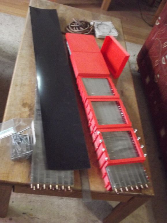
New Indoor-Outdoor Heat Exchanger for OLAHP
 3D
printing baffle boxes to direct the air flow of this unit across
the fins seemed like a great idea. I didn't count on the sheer
time involved when around 20 boxes are needed and they take almost
four hours each to print. One doesn't just start a 3D print and
then leave it unsupervised, so to a large extent it's my time as
well as the printer's. Plus the amount of printer filament such
prints would consume.
3D
printing baffle boxes to direct the air flow of this unit across
the fins seemed like a great idea. I didn't count on the sheer
time involved when around 20 boxes are needed and they take almost
four hours each to print. One doesn't just start a 3D print and
then leave it unsupervised, so to a large extent it's my time as
well as the printer's. Plus the amount of printer filament such
prints would consume.
Plus I went through several designs of baffle box
before I settled on one that I liked. But I only have about four
"duds" that I won't use. Next I have to design different boxes for
the ends, and for the middle section that ties them together. So
the printing continues into February!
 Then
there's the plumbing aspect of the work. I have to solder the 14
pipes of each heat exchanger together with 180 degree bent over
pipes in the middle.
Then
there's the plumbing aspect of the work. I have to solder the 14
pipes of each heat exchanger together with 180 degree bent over
pipes in the middle.
And I need to make four "plenums" each tying seven
pipes together. And the plenums themselves are two pairs that need
tying together and connection to the compressed air input and
output.
Much of the necessary piping work is planned out, but
not all. Can I really make all these things, solder them, and have
them not leak? "The devil is in the details" as they say. (Reminds
me my solder spool is almost empty. Do I have another one around
somewhere?)
Faraday Cabin
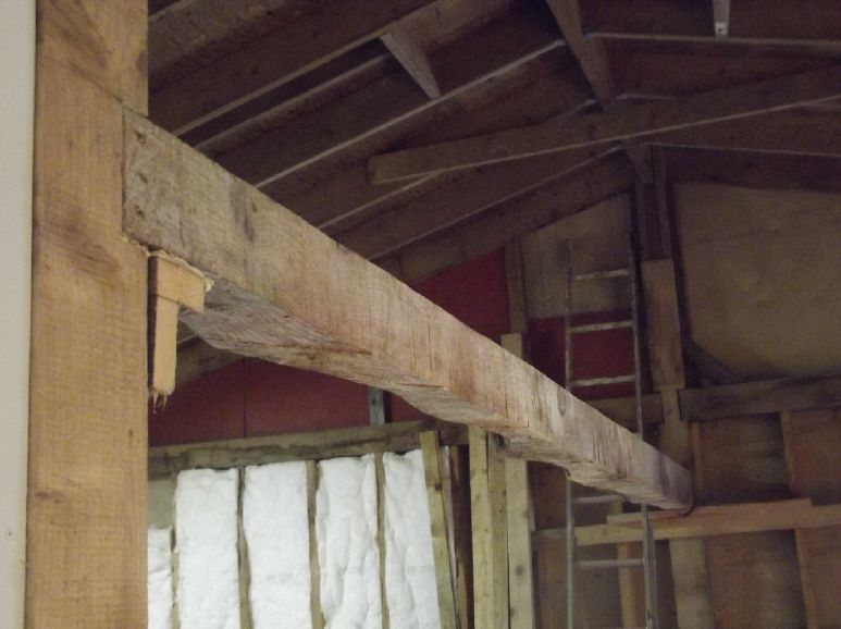 The chief
work on the cabin was to put up an ugly 16 foot long 6" by 6"
beam. (only one I had that long) I'll put in some 1/8" steel
plates to ensure the beam can't separate from the notches in the
posts (in an earthquake or something), then remove the extra
support lumber.
The chief
work on the cabin was to put up an ugly 16 foot long 6" by 6"
beam. (only one I had that long) I'll put in some 1/8" steel
plates to ensure the beam can't separate from the notches in the
posts (in an earthquake or something), then remove the extra
support lumber.
The east ceiling rafters, 12 foot long 2" by 4"s, will run
from the north wall and the south wall to this center beam under
the roof ridge. (Total area covered ~16 by ~24 feet.)
I ordered the 2" by 4"s (red cedar) at a local
sawmill and picked them up in early February.
In
Passing
(Miscellaneous topics, editorial comments & opinionated rants)
Unrest: Venezuela - Iran - Donbass - USA
Well, the year certainly started with a political
bang! Venezuelan president or dictator Nicholas Maduro was
arrested or kidnapped by American forces in an amazing military
strike or a cowardly action. I wasn't sure what to make of this
because of diametricly opposite reports. Maduro was legally
elected. Maduro lost the election but claimed he won and stayed in
power. Maduro was innocent of wrongdoing. Maduro was a
narco-terrorist leader of cartels. Venezuela's economy had
collapsed because of American sanctions, apparently placed on it
because Maduro's predecessor, Hugo Chavez, had nationalized the
Venezuelan oil industry without compensation to the owners.
Venezuela's economy had collapsed because of mismanagement and
Maduro didn't care.
A Venezuelan-American actor, Raphael de la Fuente,
said Maduro had murdered thousands of people for speaking out and
had hundreds of political prisoners in jail. Over 1/3 of the
entire population, 8 million people, had fled for survival. It was
the world's second largest population displacement crisis after
Syria. Everyone in his own extended family had lost everything. He
said that Maria Corina Machado had won the last election and that
her team had smuggled out the election certificates that showed
she had won and shown them to President Trump. And that she had
donated her Nobel prize to Trump. Fuente said foreign forces from
China, Iran, Russia and Cuba had been operating freely inside
Venezuela - that it was already invaded. It has not now been
"invaded" but "liberated" and that that was necessary for peace in
the Western hemisphere - to prevent further infiltration by forces
of authoritarian regimes.
Fuente's impassioned speech, and videos showing
Venezuelans (exiled and at home) rejoicing and dancing in the
streets, rather convinced me that what was done must be a good
thing regardless of protestations from those drawing premature
conclusions or having vested interests in the "status quo" - which
include the above mentioned regimes.
But what comes next? How does a whole state pivot
suddenly from seeming to be a criminal enterprise run for the
benefit of a few, with a boot on everyone's necks, to a
flourishing economy and democracy? I don't see how it can be an
easy, swift or sure transition.
Sure enough, a couple of days later the promoted vice
president and Maduro supporters were "cracking down" on
Venezuelans who had been publicly celebrating Maduro's arrest. One
wonders if anything will change at all!
-----
And now entering into the month, on the 8th and 9th
Iranians fed up with neglect and mismanagement by the Islamic
regime that seized power in 1979 were in the streets trying to
bring down the regime by any means necessary. They had no weapons.
The regime said they had killed over 3000 protesters to restore
order, but most other estimates are that 12,000 to 30,000 or even
43,000 or more had been killed by the IRG (Islamic Revolutionary
Guard) and way over 100,000 wounded or imprisoned - many of whom
would probably die or be killed later. Some were scheduled to be
publicly hanged, but after threats by Trump they were said to have
been killed quietly in prison instead.
Information has been scanty as an internet blackout
was imposed by the regime. They shut down everything, and
interference generators put even GPS and Starlink systems out of
action around the country. Horrific cell phone videos have made
their way out regardless. Many mosques (centers of interrogation
and detention) were burned down. There have been failed rebellions
before, but finally with shortages even of drinking water, the
unarmed Iranian people tried hard once again to overthrow the
radical Islamists running their country. One wonders how Iranians
in the IRG could so heartlessly slaughter so many of their own
people, but apparently the Ayatollah had brought large numbers of
arab mercenaries into the IRG, to whom Iranians were just faceless
non-arab foreigners. Later in the month Iranians seeking the
bodies of their slain loved ones watched in disgust as body bags
were dumped upon body bags in the morgues.
Suspicious fires and explosions from unknown causes
have continued.
As best I recall or understand of its modern history,
Iran became independent from joint rule by the Soviet Union and
Great Britain after the second world war. There was an election in
1948, but the CIA installed the Shah instead, with the newly
elected leader fleeing. When The Shah, who ran a secular
government, left the country to seek medical treatment in 1979 the
Islamic revolution took place. But it seems the Iranian people
soon discovered helping to install this new regime was a mistake.
The Shah's reign is now looked back on as a time of peace,
prosperity and liberty, and many Iranians are calling for the
return of the Shah's exiled son as the crown prince, as being
possibly the one person who could command authority and keep order
for a peaceful transition to democracy in the chaos that is
otherwise certain to follow the overthrow of the ayatollah.
Considering the apparent state of the infrastructure, the growing
hatred of the regime and of Islam, what comes next is likely to be
more tragic death regardless of the direction that finally
manifests itself.
As of the start of February the Americans have sent a
large military force to aid the rebellion, China and Russia have
reportedly sent arms to help prop up the regime against foreign
interference, but nothing much except slaughter of the protesters
has happened so far. China and Russia have a great stake in
keeping things the way they are. China gets 15% of its oil from
Iran, and Russia has been importing drones from Iran to help in
their Ukraine operations.
Some say toppling the radical Islamic regime in Iran
and bringing in democracy could bring a whole new era of peace and
stability to the whole Middle East. Tal Oran "The Traveling Clatt"
(Israeli) on youtube claims that Iranian and Jewish people have
affinity for each other and he has many Iranian friends. The
animosity comes only from the Iranian Islamic regime. And the
Iranian people are apparently much more ready for democracy than
the Arab peoples. After all they already elect a parliament, tho
it presently has little power.
Daniel Davis on Youtube had a different take. He said
the protestors hating the regime represented a small minority and
also that a quick strike like in Venezuela wouldn't be possible;
that American military action would would end up being long and
bloody and would inevitably end up with American troops on the
ground and many casualties. And that it could drag in the whole
Middle East and perhaps Russia and China. He said the protests
had, as the Ayatollah claimed, been egged on by the problems of
American sanctions and that far from "no deal", there had been a
deal under Obama. (Trump cancelled that deal in his first term,
apparently saying it was basicly a "no deal" deal - that Iran
hadn't really agreed to anything, which is also a view I remember
hearing at the time.)
Despite all its weapons, electronics defenses and
jamming, an aircraft carrier is a huge target and the Islamic
regime in Iran is heavily armed. I'm wondering myself if despite
all the military build-up, the Americans might not end up with a
bloody nose in all this and fail to topple them.
---
And speaking of the Russian invasion of the ethnic
Russian areas of Ukraine, I watched a video by Patrick Lancaster,
perhaps the only American journalist (independent) actually on the
ground in the Donbass, who had been interviewing people on the
street in Donetsk city. After much strife Donetsk and Lugansk
provinces declared independence from Ukraine following the 2014
coup in Kiev (or Kyiv) where the elected president (Yanukovich)
was cast out and fled and an American pre-picked cast (headed by
Poroshenko) was installed without an election. Indiscriminate
shelling of the cities by Ukraine from 2014 to 2022 had killed
something like 14,000 civilians in "Donetsk People's Republic" and
"Lugansk People's republic".
These provinces succeeded in breaking away because
1/3 of the small 2014 Ukrainian military went over to them. Harkiv
(or Kharkov) and other ethnic Russian provinces (or "oblasts")
were unsuccessful at breaking away, also much of the territory of
Lugansk and Donetsk was soon recaptured by Ukraine.
Lancaster says he wasn't "cherry picking" the
interviews or interviewees. He just walked up to people and if
they wanted to talk, said that the western media said Russia was
"occupying" their cities and territories - what did they think of
that? The people he talked to universally spoke along the lines
of, no, Russia was "liberating" their towns and territories from
oppressive Ukrainian "occupation". Russia brought food and water,
granted citizenship, paid pensions to the elderly and gave out
passports. The "captured" or "liberated" cities were being
rebuilt. Mariupol in particular has been largely reconstructed,
services restored, and given new life since the battles there in
2022.
Obviously the citizens of the disputed and "captured"
areas would never accept Ukrainian rule again. They formed
militias in 2014, which are now fighting alongside the Russian
army. I am ashamed that my government is supporting Kyiv's
military vendetta and obstructing the obviously desirable
realignment of administrations. We never got a vote on that and
many other things in our own somewhat 'democracy'. And if Kyiv
hadn't been aggressively trying to subdue and recapture these
clearly non-Ukrainian territories gifted to its administration
when it was all part of the Soviet Union, Lugansk and Donetsk
might well have remained as new independent, unaligned nations
instead of being driven into Russia's arms. Russia intervened
militarily only at the last moment, amidst a crescendo of
Ukrainian artillery attacks on Donetsk and Lugansk, refugees
streaming into Russia, and apparently about a week before a
planned major Ukrainian offensive intended to beat the rebel
Donbass republics into submission. But Russia struck first, so
they are the aggressor. Right?
---
With the new federal leadership in the USA seemingly
changing the focus of the DOJ and FBI from attacking political
opponents to attacking crime and lawlessness, it is astonishing to
see the number and scope of corrupt schemes at state levels being
uncovered, aided and abetted by state officials and politicians
"looking the other way" in exchange for kickbacks. Day care
centres with no kids. Hospices and medical centres with no
patients. Doctors bribed to write phony prescriptions. All these
by the dozens and even hundreds. An illegal alien buying mansions
and fancy cars with money (24 million $, was it?) gifted to him to
help the homeless. Huge sums of money being wired to Somalia.
Apparently as well as illegally residing Somali syndicates, in
other US states there are Russian and Armenian mafia involved in
many scams. Signs in Cyrillic and Armenian writing on buildings in
US cities lend credence to this claim. Whistleblowers can see what
is happening but they are ignored by state officials. An
independent journalist has now filmed lots of these
non-functioning "storefronts" in one state and published the
videos. Anyone who looked could have seen they were just
addresses, not real businesses, but the government giving them
everyone's money never did. There are photos of some of the
recently uncovered scammers with state governors and other
officials. The chance of getting funding for a legitimate
enterprise is very low. Honest people and businseses aren't
"trustworthy" to the dishonest - and they probably wouldn't even
offer a "kickback". "It's not what you know, it's who you know."
they say.
These scams appear to be amounting to at least tens
if not hundreds of billions of dollars - aid money intended to
help poor Americans is making scammers rich while more and more
Americans can't afford child day care, health care or are living
in campers or on the streets - almost a million people in cars and
campers now, I heard. There are many with jobs, but they still
can't afford to rent or buy a fixed abode of any sort. The more
there are, the more other Americans are willing to donate "to help
them." But that's not where the money goes. The
"homeless-industrial complex" it is being called.
With so many scams being shut down, one wonders if it
might not end up causing a notable reduction in the entire overall
US federal budget. (And one wonders if corrupt Federal
administration had continued whether USA would have started to
look something like Venezuela in a few more years. Certainly the
great majority was becoming increasingly impoverished.)
In turn these states' leadership convince many that
the federal government is an authoritarian dictatorship sending
the "gestapo" to enslave them and deport "your neighbors" - "It
might be your family next, or you." "We must fight back!" State
police are told to "stand down" and not cooperate. They release
criminals onto the streets rather than turn them over to federal
custody, so federal agents have to hunt them down again in public.
And some people are convinced to go out and interfere with the
federal police forces and prevent them from doing their job. Some
are even paid salaries to go out and stir up people "against
Trump", indirectly via "non-accountable government organizations"
(NGO's) by certain ultra-rich people (but mostly using "laundered"
taxpayers' money, not their own).
In fact most of those being taken have arrest
warrants outstanding for violent crimes and many of them are also
illegal aliens. There are lots of eager people applying to join
ICE. Under Biden, Venezuela emptied out its prisons and sent the
gangs north. And finding one innocent American accidently deported
among the 10 to 20 million people who illegally entered the
country in 2021-2024 (later returned, no doubt) is grounds for
saying "See? Gestapo! It could be you next!" Mistakes should never
be made, but is it realisticly possible to avoid a rare one? And
with often paid agitators continually in law enforcement's face
specificly to interfere with them doing their duty, is it any
wonder that the occasional person - agitators and officers - gets
hurt or killed?
Violent crime in the year since Trump took office is
way down, especially in some areas. I saw percentages like 28, 40
and even 60% reduction for various forms of crime. In some cities
people apparently say they feel safe to walk on the streets again.
How could it be that deporting or locking up a whole host of
violent people with criminal records doesn't play the key part in
all that?
Scattered Thots
* Invention wanted: A locking crescent wrench that
only adjusts when you want it to. It seems that whenever you get
one adjusted right and make one part turn of a bolt or nut, when
you reposition the wrench it has somehow changed and either won't
go on again or is too loose. On the rare occasion that doesn't
happen, you think it has anyway because you haven't got the
rotation quite right, and so you end up adjusting it anyway. Every
bolt or nut. Every repositioning. Sometimes they come loose even
while turning one. A crescent wrench that would stay locked where
it was put would be enormously helpful.
 * An interesting video
showed deaths and incidences of cancers. Incidences of most
cancers were lower for people who got some sunlight every day
(left) than for people who didn't. (right side) The top bars were
"all cancers".
* An interesting video
showed deaths and incidences of cancers. Incidences of most
cancers were lower for people who got some sunlight every day
(left) than for people who didn't. (right side) The top bars were
"all cancers".
Skin cancers were the bottom two bars, by the orange
arrow. They show that there's very low chance of dying of skin
cancer whether you get sun or not, whereas other cancers that
cause far more deaths were much reduced by getting enough sun,
which of course allows the body to make vitamin D in/on the skin.
As mentioned in the previous issue, most of us are
vitamin D deficient unless we take vitamin D daily or get enough
sunshine. 1000 IU pills are common and the most often suggested.
(No, I can't read the words in this chart either. It got
shrunk somewhere along the line. I'm going by memory from the
video.)
* Well, here's a very nice keyboard, but with an itty bitty hidden
on-off switch! I thought it was a tiny case screw. No wonder it
didn't work!
CCK (was once "CSK"): Carmichael Computer Keyboard
* I still have hope that someday people will remember that the
"Qwerty" key layout was essentially designed to slow typists down
so they wouldn't keep jamming up the keys on the earliest
typewriters in about 1876, and will pick another layout. Perhaps
mine, the "Carmichael Computer Keyboard" (CCK), specificly
designed in 1986 for fastest computer typing and text editing
rather than for typewriters -- rejected for development funding by
NRC/IRAP like most more economical things that might actually
improve the world.
And I hope that manufacturers will at last notice the
keys don't attach by levers to the top of the keyboard any more,
so the key columns don't have to be verticly staggered any more.
Dr. August Dvorak created a better typewriter layout
in the 1930's which almost got adopted in world war two, the
"Dvorak Simplified Keyboard" (DSK). After having rapidly trained a
pile of military typists on Dvorak, the order for hundreds of
these easier to learn, faster to type on typewriters was cancelled
by some bureaucrat in the procurement department because they
"weren't standard". But ever since, "the world's fastest typist"
award consistently went to any of the very few Dvorak typists. I
started from his much better but not entirely optimal layout and
improved on it, with further modifications for easier use with
computer text editing instead of typewriters.
Typists who've learned on qwerty need never change,
but young people would be quick to adopt something so obviously
better. Just seeing all the vowels on the home row of the left
hand they would instinctively sense that it will be easier to
learn and faster to type. Then they would look closer and notice
other advantages, and see it as the future.
(See also
TENews #5.)
Here is another version of the keyboard, one of two that I used
to type on for many years,
this one on pre-USB Macintoshes, typing and finding remaining
annoyances to hone the layout.
The alphabetic layout is of course the most important thing.
The digits (Dvorak's layout) make touch-typing sense to the
fingers instead of to the eyes.
I moved keycaps around, but of course not all the keys could be
properly labelled.
The key between "P" and "X" is "TH", which is as common as all
other uses of "H".
(Ideally if making it I would align the keys verticly. I'd put a
small gap between left and right hand keys for easier feel.)
The SHIFT key (just tap to shift next letter only) is on the
left thumb. (Needed esp. for "Th" key.)
BACKSPACE is to the left of "O" on the left little finger - very
intuitive.
For the UP DOWN LEFT RIGHT arrows just move the left fingers
straight down one row from home -
Cursor arrows in touch-typing positions! (Labelled:
shift ' , . )
RETURN on the index finger, diagonally up from "I" & next to
"F", is also far more convenient than way off to the right
on the little finger. ...I could type and edit really fast!
(Alas there was no ready way for me to "hack" USB keyboards and
I had to learn
to type the hated "qwerty" layout over again when I started
Turquoise Energy)
There is much more to say about the design and layout
of the keyboard and the rationale for each key and placement. For
example, my self-created computer app program studies of frequency
of letters and frequency of two letter combinations in English.
For example, two letters that are frequently typed consecutively
(ng, sh, st, nt ...) shouldn't be on the same finger, nor should
typing the first one pull the hand out of position for the next.
Putting all the vowels on the left hand greatly facilitates this
since consonants and vowels are so often interleaved. We are now
in 2026 almost as far ahead in time from my keyboard in 1986 as
that was from Dvorak's layout, or Dvorak's work was from Shoales'
original typewriter in 1876.
A New Promotion of CCK Keyboard?
But writing this blurb gives me a new idea (Oh, no,
not another idea!): To explain and promote the keyboard, I should
do a video about it and put it on youtube. I'll never find the
time to study USB protocol programming and make an actual working
keyboard again, much less "from scratch" with the keys
straightened out, but I can at least do a drawing of my most ideal
layout. Perhaps someone will see it and be inspired, and catch the
ear someone who could manufacture them. Keyboards are made by the
tens of millions. One that sets itself apart by obvious
superiority would be bound to sell well to the young.
Manufacturing is so much easier today that we should all have more
and better choices, not just a hand-me-down from 1876.
Electrosmog Department
(I can't seem to get away from this topic, so here's it's
own place!)
I received and connected the "power line modulator"
ethernet connectors. But the next night the cabin was making
tinnitus again. Hmm... the ethernet cable from the AC plug-in at
the far end ran alongside the heaters extension cord. Furthermore,
with the computer unplugged it wasn't grounded - at least not at
the bedroom end. The power line adapter end was probably also
floating. Seems any ungrounded wire will pick up the field from a
nearby AC wire and carry at along. I added a power switch to the
tin can (Orange PI zero 3 SBC) computer so I could turn it off but
leave it plugged in and so grounded.
After having the electric heaters apparently tamed, I
realized they were still bothering my ears at night - really the
main culprits. I found I had unplugged one of the wire grid
grounds from the outlet for something else, but plugging it back
in didn't seem to help. I unplugged the heaters (1300 W) and just
went with 400 watts of DC heaters for a couple of hours. That
finally seemed to help, but it was getting cold. Was there a bad
connection to one of the shielding screens? Or was I just
imagining that I was getting relief in such a short time, when
tinnitus takes days to really fade away?
[27th] In bed in the middle of the night I suddenly remembered
that the cabin's garage door, while metal on the outside, hadn't
been grounded since I was working on the mechanism for it to open,
well over a year ago. This was a much bigger opening for
electrosmog than the two windows on the same west side of the
cabin! It explained why the extension cord outside that wall, and
perhaps even the WiFi from the house, might have a notable effect
inside. I connected a wire to it, long enough to stay on with
slack when the door was opened and closed.
[February 2nd] Along with all the things I've been doing, I
finally ordered a conductive canopy with silver fibers for my bed.
(750$ or thereabouts) It's supposed to drop RF signals by 20 or 30
dB. I'll see what positive effect that might have inside an
already shielded building. At least it might help against those
heaters. Definitely the amount of power in use - creating the
magnetic field - has a big effect as well as the voltage field.
How much is 20 dB? -3 dB is half power, while -6 dB
is half the perceived volume. But! In 1975 we had a control
signal, a tone, that didn't seem to be getting through a phone
line to a piece of equipment at Port Hardy Airport. They sent me,
the new 20 year old, alone to work with two BC Tel techs. We went
to the transmitter site and I listened with headphones at the BC
Tel demarcation block. The tone was loud and clear. Then they
stayed there while I alone went inside and listened at the
equipment. I could hear it fine but it just didn't seem as loud. I
came out and one asked "Could you hear it?" "Well, yes..." I said.
"Not our problem then. Hah, I knew it!" (Dumb civil servants!) and
they drove off. Then I used a Vu meter and found the volume of the
tone was down 20 dB inside. Tracing further, one wire wasn't
connecting at the demarc block - on the BC Tel side. I pushed the
offending wire into place in the RB66 block and all was well
again. Just stray capacitance and inductance had brought the
signal through on one wire of the pair, but at -20 dB. I wasn't
confident enough in the first brief test to say definitively that
the volume was lower.
And so it is with tinnitus. Unless you can measure
its volume (a technique is in TENews #somethingorother fairly
recent), if you aren't specificly paying attention to it, you
don't really notice it's different unless it gets really loud (as
when working for hours too near the power line) or unless it fades
to almost nothing (as in a three or four day camping trip away
from all AC electricity/radio/WiFi/Cell phones..., perhaps). In
just a day trip to the wilds (even with no cell phone, etc), the
small drop in intensity probably isn't enough to clue you in that
it's AC electricity causing your tinnitus.
[Feb 5th] Draping a grounded conductive cloth over me in bed
helped, but was a nuisance. Now I hung the cloth from the ceiling
past the foot of the bed so it was between the bed and the
heater(s), again grounded. Three layers of shields between me and
the heater finally seemed to do the trick. More or less. Warm
weather, unplugging the heaters and taking away the extension cord
will probably work better.
ESD
(Eccentric Silliness Department - No electrostatic
discharge)
* Is palm oil the same thing as finger grease?
* An ice day just isn't the same thing as a nice day.
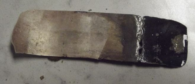
* Alchemists sought to turn lead into gold. I've become a
"nochemist". I've turned shiny pure silver into black mush!
"in
depth reports" for each project are below. I hope they may be
useful to anyone who wants to get into a similar project, to glean
ideas for how something might be done, as well as things that
might have been tried, or just thought of and not tried... and
even of how not to do something - why it didn't work or proved
impractical. Sometimes they set out inventive thoughts almost as
they occur - and are the actual organization and elaboration in
writing of those thoughts. They are thus partly a diary and are
not extensively proof-read for literary perfection, consistency,
completeness and elimination of duplications before publication. I
hope they may add to the body of wisdom for other researchers and
developers to help them find more productive paths and avoid
potential pitfalls and dead ends.
Electric
Transport (No
Reports)
Other
"Green" & Electric Equipment Projects
Open Loop Air Heat Pumping (OLAHP)
Indoor-Outdoor Air Heat Exchanger
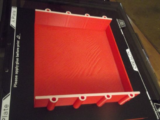
[24th] Over the weeks I 3D printed some "baffle boxes" for the
exchanger from ABS - air directors to get the air to flow back and
forth through the heat exchanger fins as it moves along their
lengths. The early ones had a tendency to split at the seams, so I
made the walls thicker, then thicker again. They took so long to
print that I decided to cut a long piece of sheet ABS for the
outside face and skip printing the box faces. Then I got the idea
to put in holes for bolts to hold everything together. Now they
took over 3 hours (each) to print even without the face. On the
first two of those, the holes were too small for #10-24 bolts, so
I changed it again. Then I made another small change and (for at
least the second time), the computer did an I/O error saving the
g-code file. I've never seen anything that makes so many errors in
recent times as the Lenova saving files to USB memory sticks.
(Hmm... it might be one brand/model of memory sticks.) There's
nothing more aggravating than the printer stopping two and 3/4
hours into a 3 hour print with just a few layers of walls left to
go, saying "Character encoding error in g-code file." (Okay, there
are surely more aggravating things, but it ranks up there.)
It's bad enough when an image file doesn't come out.
At least you can see that part of the jpeg image is missing.
There's really no way to tell with the g-code files unless the
printer stops on line 45,826 or whatever. It's text but it would
be ludicrous to try to proof read it.
So anyway I have one box I'll use so far out of about
8. They take over 3 hours each (all going well) and there's about
20 to print - 70 hours of printing - then I'll need some special
ones for the ends. I won't be finished in January.
I also thought about how I was going to combine the 14 little
compressed air pipes into one big one. I cut a 1 inch copper pipe
for the end of one section. I have a special punch idea - one that
will leave "walls" around the hole edges for making the 7 pipes of
each row solder reliably into the big pipe with regular soft
solder. I annealed the large pipe so it can be formed and punched
without cracking.
[28th] I decided it was silly to need the piece of ABS sheet. I
made the next design with a solid cover again even tho it took
over 3-1/2 hours to print. I printed two this day, the ninth and
tenth. I'll glue individual ABS covers to five of the previous
designs and thread the holes of the two whose screw holes are too
small. With that there's almost enough now to cover one of the two
finned radiator units. I'm finally really happy with the latest
design. The other radiator unit will of course need 10 more
baffles, and I still have to design special ones for the ends of
the units. I never suspected this was going to be such a long
drawn out process!
 The red ABS filament spool was running
out just before the end of this print.
The red ABS filament spool was running
out just before the end of this print.
I was watching it and grabbed a spool another spool (white) and
fed it in by hand right behind the
end of the red and so got it to finish instead of screwing up
after 3-1/2 hours just before the end.
(Pfew!)
Baffles on January 31st.
Efficiency Tips
"Ziroth" on youtube did a video called The Genius of the
World's Most Efficient Heat Pump. The title picture showed
"800% efficiency". The title was a bit misleading. It was about
tweaking existing heat pumps to get the best performance. The much
tweaked heat pump got an "ultimate" COP of 8 in September, which
means it wasn't very cold out. In the video COP's of 2.5 to 5.5 in
cooler weather were mentioned. I have the grand new OLAHP design,
but I'm no expert, so I took note of the tips.
1 & 4: Two variants of "Modulate the system so it's doing just
enough all the time, rather than switching on and off." ('A car
doing 90 MPH and resting 2/3 of the time will get from Land's End
to Scotland in the same time as a car doing a steady 30 MPH, but
it'll use more petrol.' [Actually, as typical gasoline cars work,
driving around 40 MPH will use even less petrol per mile
than driving 30 MPH. 90 is still way more.])
2: Use piping with the least resistance to flow so the compressor
doesn't have to work as hard. This would apply to air (compressed
or not) as well as to refrigerant. Fat pipes, smooth curves, no
bottlenecks at valves, copper better than plastic pipes.
3: Balance radiators. (I don't expect to be having two radiators
in my prototypes!)
5: Measure outdoor temperature so as to modulate heating as the
heating load changes before the indoor temperature starts to
change.
6: Design the hot water heating setup just carefully, water no
hotter than necessary.
7: Correctly size radiators and heat pump for expected heating
loads.
I had always thought that that heating hot water with
a heat pump sounded silly since hot water has to be so much hotter
than room air. But... Hot water can be set as low as 38 to 40
degrees. One simply runs mostly hot water for showers. (As I
already do - the water tank will last longer. Why have scalding
hot water?) A bigger tank (if needed) kept at 40 degrees isn't so
much warmer than a room air radiator at 35 degrees so the COP for
heating the water won't be much lower. So far I have no plans for
incorporating water heating into my prototypes.
Hmm... In several comments below the video people
said that wasn't hot enough, that at 40 degrees (AKA 104 degrees
F) the water could support "Legionella"(?) virus, "Legionaire's
disease", which can be fatal if swallowed. I think they were
saying 55 degrees (130 degrees F) was a minimum temperature for a
hot water tank. (My own well water has enough sulfur to kill
anything. Still now that I'm thinking about it I wouldn't want my
hot water below about 50 degrees (120 F) minimum.)
Someone suggested that if the OLAHP heat pump was
putting out decompressed cold air colder than the outdoor
temperature it might be used in a refrigerator or freezer before
being released. Theoreticly that should work, but it would be
dependent on it being - at least - cold enough outside to be
running the heat pump. In the summer the idea fails.
Of course it should also work with OLAHP used in
reverse, as an air conditioner. In that case, the decompressing
air would be released into the fridge and from there into the
house to cool it, instead of outside. But in the case of OLAHP,
the equipment for air conditioning would all be reversed and
probably installed outside the house, and again the fridge or
freezer idea only works if it's running.
Pipe Joiner "Plenums"
 The other
main jobs are plumbing: connect the two radiators together into
one (folded over) long unit with 14 curved pipes, and four
"plenums" each to connect 7 pipes into one at the ends.
The other
main jobs are plumbing: connect the two radiators together into
one (folded over) long unit with 14 curved pipes, and four
"plenums" each to connect 7 pipes into one at the ends.
For the latter I cut a piece of 1 inch copper pipe,
annealed so it could be worked, and flattened it into a tall
narrow tube with steel bars to give the desired shape. To make two
plenums connecting 7 pipes each with the two rows of pipes so
close together, the plenum pipes will have to be thin. But they'll
have quite a lot of moving air, so they do need some volume. So
make them flat ovals. (Per the "efficiency" guide above, bigger
pipes for less resistance.)
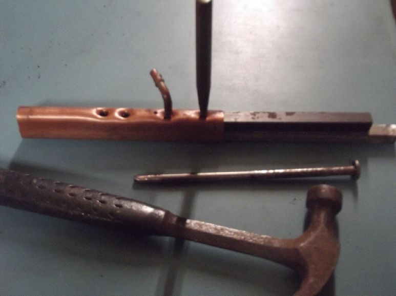
My strategy then is to make holes to solder the ends
of the seven pipes into, 21 mm apart, along a thin edge of the
plenum. I tried different sizes of holes in the steel bar and
different size punches. By punching holes into the recesses in the
steel bar instead of drilling them out, I hoped to get holes with
walls to solder the pipes to. There is at least more material to
solder to than the thickness of the wall.
With the first hole too big - the small pipe fit in
too loosely - I realized that this was going to be a practice
unit.
The basic technique is:
* shape the plenum pipe [hmm, better rectangular?: flat top and
bottom rather than oval?]
* insert a 1/2 by 1/2 inch steel bar
* above that insert the bar with recess holes in it. There should
be at least two holes, exactly 21 mm apart to match the spacings
of the seven pipes.
* drill a small hole where the pipe hole is to go. Pound in the
center punch to open the hole, creating tapered sides. (as shown
above & below)
* Punch again with the ground-down nail to expand the hole walls
to the right size for the pipe.
* Use the second hole in the steel bar to make the second hole in
the plenum pipe.
* Remove the lower bar. Now the upper bar with holes can drop
down, clear of the hole walls it has made.
* Move the upper bar along by one hole, so that the first hole in
the bar centers itself on the walls of the second hole in the
pipe, ensuring that the holes will be exactly 21 mm apart.
* Insert the lower bar and punch out the next hole.
* Repeat until all seven holes are made.
These are probably [just] good
enough, but I hope to improve the technique and get deeper,
straighter walls in the pipe around the holes.
Now... about the ends of the flattened pipe and the
external connections??? I may have to shape some pretty fancy
pieces of copper!
"Faraday
Cabin" Construction
The idea for the 10 foot
high ceiling for the east side of the cabin was to put a 16 foot
beam across under the peak of the roof, and to set 12 foot 2" by
4"s on top of a board on the wall at one end and on top of the
beam at the other, making two ceilings almost 12 by 16 feet.
On a nice day I dragged out the 16 foot 6 by 6
(roughly) beam for the center of the ceiling from the middle of
the lumber pile under metal roof pieces outdoors and brought it in
through the garage door. It's not the most beautiful timber, but
it was the only one I had that was so long. To fit it I cut just 3
inches off one end. I still haven't finished the garage door and
it fell off when I opened it. Between disassembling the lumber
pile, dragging the beam inside foot by foot, and setting the door
back in place in the wall in "closed" position, it took all
afternoon.
[26th] While I was
cutting the notches in the posts, my retired carpenter friend Dan
Bellis showed up with ideas, skills, tools and an extra hand for
the lifting. He screwed various pieces of wood into place to hold
the beam. And we put up ropes to tie it up once an end was lifted.
We lifted one end onto an upturned table and then the other end
onto a cross piece screwed into the wall studs. After a second
cross piece at the other end it was high enough to get one end
into place. But with the odd shaped beam the post notch needed
some extra gouging out, which I did with a battery electric
chainsaw on a stepladder, all with the beam end touching the
notch. Not my favorite working condition!
When I was done, a good shove pushed it into the
notch.
The other end was persuaded to start to go in with a
pipe clamp, and once started into the groove, with a hammer.
I'll put some 1/8" steel plates with lag bolts to
securely hold the beam to the posts, then remove the pieces of
wood.
[27th] Abfam sawmill didn't have 12 foot 2" by 4"s. I went to
North Pacific Timber sawmill and ordered thirty 2" by 4"s. He said
they were cutting red cedar this week, so that's what I asked for.
I wanted to use stronger un-planed full 2" by 4" dimension wood
rather than planed 1.5" by 3.5" pieces from the retail lumber
yard. Later Dan suggested a couple of other local sawmills I could
have gone to. (I picked up the wood February 5th. They gave me a
good deal.)
Haida Gwaii Gardening
(Not much of a Report)
I sold my three coffee trees. They were taking
up too much indoor space except in summer, when I would put them
outside or in the greenhouse. One was nearing the dining area
ceiling. The other two were in front of a cherry tomato in the
livingroom window, which had flowers but almost no tomatos,
probably owing to neglect because I couldn't get near it to
pollinate the flowers with an art brush. My two pepper plants,
both about 3 years old, were on my cold dining area floor (in
freezing weather) instead of in the livingroom window, again owing
to the coffee trees, and although there were LED lights there,
they died doubtless because of the cold, along with another cherry
tomato. (The banana peppers are sweeter than the orange
mini-bells. They are long and thin, but they turn red.)
I offered to give away the coffee trees, but my
friend Dan Bellis insisted on paying me for them. I never thought
of them as a "cash crop"! He said they were just what his
daughter's big new house needed and they were very pleased with
them.
I started a "hot red cherry pepper" (only a little
hot) late last summer and so far it is surviving in the livingroom
window. Maybe I'll try starting a couple more peppers in the
spring. This time I'll be sure to keep them warm. They may grow
once started, but they don't seem to germinate unless in a warm
place and I have repeatedly failed to start new ones. Owing to the
cold I put a plastic bag over it, but that seems to have killed
it. Maybe it got too hot when the sun finally shone? Aphids were
also a big problem on this plant. It made one tiny pepper, which
did turn red. It was much hotter than I remember them being, but
not "red hot". I got a few tiny seeds for trying to grow another
one.
[8th] I thought about ways to
electroplate graphite. Silver nitrate is usually used to plate
anything and everything with silver, without electricity. (I
remember doing a 6 inch telescope mirror at Malaspina college in
1974, with the assistance of a chemistry professor. (Of course, I
was taking electronics and that was my only interaction with the
chemistry department. They supervised because silver nitrate can
apparently turn into silver fulminate, which can detonate
spontaneously!) I had made the mirror in 1972 when I was in high
school, then we had moved from Edmonton to Fanny Bay on Vancouver
Island before I could get it done.)
One could make silver nitrate with silver and nitric
acid, but silver nitrate solution plates everything including the
container. If one only wants to plate a thin layer on graphite,
this would be a great waste of silver. So I thought I would try a
different approach.
I filled a 100 cc beaker to 50 cc and added 10 grams
of sodium nitrate. I attached a "plus" leed to a piece of silver
and put it in. Then a "minus" leed to a piece of graphite gasket.
I set the power to 1.0 volts and left it overnight. Current was
small, starting around 5 mA and dropping to 2. The silver was a
little discolored and the solution was a little cloudy, but the
graphite appeared unchanged.
[9th] I added .5 gram of sodium hydroxide to make it
alkaline. Current was just 1.1 mA. If anything was going to
happen, it would be slowly.
[10th] With the hydroxide the silver was definitely oxidizing, and
perhaps due to the nitrate some oxide was precipitating off the
silver instead of just forming a skin. So instead of a dissolved
Ag+ ion like dissolved silver nitrate, I had loose silver oxide
powder. I put it in a jar lid and laid the graphite sheet on the
bottom on top of some of the black powder, and reconnected the
voltage. Maybe the graphite would touch the Ag2O and
turn it into Ag on the surface? It didn't seem to do it. After
some hours not much current, nothing was visible and resistance
readings were unchanged. Now what?
I put the assembly into a bigger beaker, added some
more water and started the magnetic stirrer, briskly, so the black
oxide was swirling around in the solution. Then I changed the
silvery graphite gasket sheet for a black carbon/graphite rod. (so
I could plainly see any silver coating.) It was still at one volt,
and dropped to under a milliamp of current. After some hours I
looked. Again I didn't see any silver plating. But I tested it.
The ohms readings on the un-immersed section were around 2.5 to 12
ohms. The readings on the immersed bottom part (dried off) were
under 1 ohm to around 5 ohms. seemingly in all that time some
invisibly thin and perhaps not continuous layer of silver had been
plated on, improving surface conductivity a bit? I left it on
overnight again, with the stirrer running.
[11th] When dried longer, the resistance readings on the graphite
were similar whether above or below the waterline. It still showed
no sign of plating any silver onto itself. Apparently this method
of plating is a failure.
How to Make Silver Oxide Without Consuming Chemicals
 BUT!
what do I have? Nano silver oxide powder! Using electricity I've
made sliver oxide without consuming anything! No nitric acid to
turn the silver to silver nitrate, no hydrochloric acid to turn it
to silver chloride, and no potassium hydroxide to turn the silver
chloride to oxide.
BUT!
what do I have? Nano silver oxide powder! Using electricity I've
made sliver oxide without consuming anything! No nitric acid to
turn the silver to silver nitrate, no hydrochloric acid to turn it
to silver chloride, and no potassium hydroxide to turn the silver
chloride to oxide.
Does that have a use? It didn't seem very conductive when I
measured it (sources saying it is notwithstanding), but it's not
an insulator, either. But what if one mixed it into a lower
voltage "+" 'trode in a battery as a conductivity additive? If
it's below silver's oxidation voltage, it should convert to nano
silver metal particles.
Silver is (by size) the most conductive element. It
would surely be better than graphite powder or conductive carbon
black! That should make for a highly conductive "+" side, and the
"+" is the "poor" side of a battery in terms of conductivity. And
if the electrode is so conductive, it might be made thicker - even
2 or 3 mm instead of under 1 mm. This would pull the amp-hours for
even my tiny cells way up! Combine the highly conductive zinc "-"
side with a "+" having maybe 5 wt% silver nano particles PLUS a
silver plated current collector, and it could be an order of
magnitude greater load current capacity with corresponding fast
charge rates, in a simple construction, low cost alkaline type
cell! ("Low cost" assuming it doesn't take *much* silver. The
stuff has hextupled in price in the last ten years! Doubled, and
then tripled again in the last few months.) So I put it back in
the small beaker for maximum depth of liquid and switched it back
on and left it running. It seemed to draw around 3 mA. Then I took
the silver out and weighed it. If the "+" electrode has say ten
grams of material, I need to produce about .5 grams of Ag2O to
match. (Yikes, that's around 1.80 $C at the present price. Oh
well, for a life-long, high energy density battery that can't
explode?)
 A secondary
thought is that moving copper to valence three is just a bit less
than the voltage of converting Ag to Ag2O.
A secondary
thought is that moving copper to valence three is just a bit less
than the voltage of converting Ag to Ag2O.
(Previous alkaline cells using silver as the "+" electrode
substance have usually started out with Ag2O2, which has an
uncomfortably high voltage that gradually destroys separator
papers and current collectors.) But Ag2O is just +.34 V at pH 14
and moves an electron per silver atom.)
Might it work out that the "conductivity additive" is
also an active electrode substance? If that's not "overcharging"?
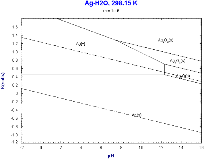
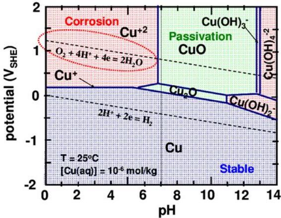 According to
these Pourbaix diagrams, with Zinc being about -1.2 volts (pH 13),
the cell might charge to about 1.5 volts including Ag2O,
fairly rapidly drop to ~1.3 when the 5% silver oxide was
discharged to Ag metal nano particles (the metal then enhancing
conductivity for the copper substance), and then discharge
more gradually from ~1.3 down to ~.9 and finally ~.8 volts before
the copper is all converted from hydroxides to Cu metal particles?
According to
these Pourbaix diagrams, with Zinc being about -1.2 volts (pH 13),
the cell might charge to about 1.5 volts including Ag2O,
fairly rapidly drop to ~1.3 when the 5% silver oxide was
discharged to Ag metal nano particles (the metal then enhancing
conductivity for the copper substance), and then discharge
more gradually from ~1.3 down to ~.9 and finally ~.8 volts before
the copper is all converted from hydroxides to Cu metal particles?
Ag2O ....... +.3V [black powder]
Cu(OH)4-- +.1V [cuprate ion. At pH 13 it might be Cu(OH)3-]
Cu(OH)2 .... -.3V [blue powder]
CuOH ........ -.4V [orange powder - not shown in this pourbaix
diagram]
Zn(OH)4-- -1.2V [zincate ion]
Cell volts:
+.3 - -1.2 = 1.5
+.1 - -1.2 = 1.3
-.3 - -1.2 = 0.9
-.4 - -1.2 = 0.8
That's a pretty wild voltage swing between "full
charge" and "low"! Even if one decided charging the silver was a
bad idea it's 1.3 to .8 volts. A DC to DC converter to keep a
steady output will be almost a must for most applications. OTOH
those are a pretty standard item these days.
At least one could easily determine state of charge
just by looking at a battery's open circuit voltage!
But the amp-hours should be phenomenal with each
silver atom moving an electron and each copper atom moving two,
and three or four hydroxyl ions, total four or five!
Nickel oxyhydroxide by contrast moves at best 1.5
electrons per nickel atom.
Half reactions on discharge (charge is right to left):
Ag2O + H2O + 2 e- => 2 Ag + <=> 2 Ag + 2 OH- [+.3V @ pH
13]
Cu(OH)4-- <=> Cu(OH)2 + 2 OH- [+.1V]
Cu(OH)2 + e- <=> CuOH + OH- [-.3V]
CuOH + e- <=> Cu + OH- [-.4V]
The idea of having not only long lasting, not only
low cost, not only "simple", but what could be a very fast
alkaline battery - after all my very slow ones - makes this even
more exciting!
[12th] With the silver oxide maker still running, I tried brushing
off the silver plate. This brushed the surface layer off into the
beaker and current went from very low to 30 or 40 milliamps. That
should make oxide a lot faster than 3 or 4 milliamps! After an
hour or current would drop substantially and be worth brushing
again.
I took apart the first ointment jar cell, breaking
the glue. (I put the zinc basket in an ointment jar of the same
electrolyte to keep it flooded.) The outer electrode with the
graphite came out with the basket and fell off. I scraped the
electrode substance off and weighed it: about 15 grams. To get 5
wt% silver oxide, I need to make .75 grams of it. It may be
getting close to that now.
Silver-Zinc?
I consider that one might make a plain
silver-zinc cell, ~1.5 volts, capable of the highest currents. But
it would only move one electron per silver atom, so the amp-hours
and watt-hours per weight would be rather low, since silver is a
pretty heavy atom. And with the price of silver now, they would be
very costly. One would need twice as many silver atoms as zinc
atoms, and they are heavier. (but nothing like lead!)
If one charged the silver to Ag2O2 it would move two
electrons - half as much silver to balance the zinc. The voltage
would be around 1.9 volts until it discharged to Ag2O, then 1.5
volts for the lower 50% of its charge state. It would probably
also demand some oxygen overvoltage additive(s) to suppress oxygen
generation. But the voltage of nickel [oxyhydroxide] is ~+.5V and
seems to be about as high as one should go, whereas silver (Ag2O2)
looks like almost +.7 . Somehow I suspect that such a high voltage
would cause other problems - perhaps oxidize the elaborate
separator paper or some component thereof.
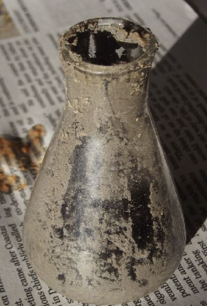
 [13th] Producing silver
oxide went much faster after I started brushing the oxide off the
silver piece into the liquid. Spinning the agitator faster also
helped a lot. It also oxidized fastest at the water line, and
later the bottom (immersed) part broke off "at the dotted line". I
now found the piece to be about 1.5 grams lighter than originally.
[13th] Producing silver
oxide went much faster after I started brushing the oxide off the
silver piece into the liquid. Spinning the agitator faster also
helped a lot. It also oxidized fastest at the water line, and
later the bottom (immersed) part broke off "at the dotted line". I
now found the piece to be about 1.5 grams lighter than originally.
I weighed the material in the electrode of the first cell -
15 grams. So 5% would be .75 grams of Ag2O. So I had lots. I let
it settle, poured off the liquid (into another beaker for next
time), rinsed with water, and dried it on the hotplate, still in
the beaker.
I still wanted to plate silver onto graphite, so I
looked it up. There were those nasty highly poisonous cyanide
solutions. In a post someone said "I vote for thiosulfate!" Quite
stable and made a good plating. I ordered some at Sigma Alderich.
Typical for me, this was too hasty. I now looked up
"how to" and found an Indian paper from a 1986 symposium with the
recipe 3g AgCl, 30-50g NaS2O2 (sodium thiosulfate) and 3+g sodium
metabisulfite, in 100cc of water. I could make AgCl (I think!) but
I should have ordered the last ingredient. Hmm, There's sodium
metabisulfite in wine making kits.
The Ni-Zn #2 cell was still way over 1.7 volts after
sitting for a week. I ran a brief test and figured it was down
probably only about as much as cells with nickel usually are after
a few days. With the power supply free again, I charged it
overnight.
[14th] I added 2cc of water to Ni-Zn #2 and ran a "10" ohm load
test and found it was about as strong as ever. (about 12 ohms with
the current meter shunt & misc. resistances - and never
exactly the same twice.) Comparing the last two long 12 ohm load
tests, it ran for 189 minutes running down to 1.00 volts instead
of 150 minutes, at very slightly lower currents. That's 26%
longer. It delivered about 350 mA-hours instead of 345. (Hopefully
those last figures will go way up with the organic-monel substance
with silver added to it instead of old dry cell nickel hydroxide.)
The cell is now over a month old, having been made
about December 14th. That's the longest lasting cell
I've made. It sure helps that they don't leak or allow
electrode material to swell badly.
I dried off the electrode material out of cell
Organic/Monel-Zn #1. It went down to ~11.4 grams. I put in .65
grams of Ag2O (5.4%) and mixed them. The silver wanted to stay in
clumps, so it took a fair bit of mixing with a tiny spoon for this
tiny quantity.
I also tried to look up how to make silver chloride
for plating. Virtually everything said to use silver nitrate and
then hydrochloric acid, because silver metal will dissolve in
nitric acid but not sulfuric or hydrochloric. Evidently silver
nitrate will convert to silver chloride. (And presumably sodium
nitrate.) I wondered if one could convert silver oxide to silver
chloride with hydrochloric acid. Nothing I found on the web said
so. Most results were about turning silver chloride to metal,
notwithstanding my pains to put it the other way around. There
were two sites about "balancing chemical equations". One said: __
Ag2O + __ HCl = __AgCl + __H2O, but another said __AgCl +
__H2O = __Ag2O + __HCl (student to figure out the quantities...
Obviously 1 Ag2O + 2 HCl => 2 AgCl + 1 H2O). Neither one said
which way around the reaction would actually go or if either one
even worked. Well, I think I'll assume it'll work the first way,
first because it's being used as an example, and then that it'll
be similar to copper -- that the oxide will convert to chloride
with HCl (hopefully at room temperature) -- rather than that the
chloride in water will convert to silver oxide and HCl because
that just doesn't make sense. That means I should make more silver
oxide, to convert to silver chloride for doing plating, since I
can't make silver chloride directly from silver metal. (I'll pass
on the nitric acid and silver nitrate.) But the plating must await
the thiosulfate.
Organic Monel-Zinc Cell Again
In the evening I redid cell #1. I compacted 10 grams
of the monel/copper substance, now with 5.4% silver oxide, into
the perimeter of the jar with the silver current
collector/terminal inside the rim. The copper pipe
plunger/compactor wouldn't fit in if I reduced the outer diameter
with a sheet or two of graphite, so just the silver.
I filled it. It started out at 1.25 volts and rising,
and put over 1/4 amp into a short circuit. I let it charge
overnight.
[15th] Performance was disappointing. With a 22 ohm load it
dropped below 1.1 volt pretty quickly and fell through 0.6 volts
in an hour. A later test ran about the same time with slightly
lower voltages through much of the range. 25 or 30 milliamp hours?
Late another test didn't start well so I stopped it. It probably
hadn't been charged long enough.
I looked up the original tests from early December.
Wow! Was I really running 1000 and 500 ohm load tests, and they
didn't even last half an hour? Nothing else was changed unless the
compaction was a bit better, so it seemed the silver current
collector, and probably more the silver/silver oxide powder as a
conductivity additive, had improved performance by something
toward 5000%!
No doubt 5% graphite powder or conductive carbon
black would have greatly upped the performance too, but not to
such an extent. I'm glad I figured out that silver would work with
lower voltage electrodes. (I still can't believe that Jungner
missed gold as a working metal for alkaline nickel electrodes!)
I should certainly go over what ingredients I used so
long ago making this electrode concoction. The chances that it was
anything like optimum proportions or had the best preparation
procedures are poor.
I thought about nickel not holding a charge below pH
13.5 and decided to try it with the copper cell. I added a gram of
KOH but didn't actually check the pH. Presumbly 13.5 .
[16th] I ran another test in the morning, 27 ohms, and left it to
run down to nothing. It was improved over the previous tests,
albeit with the 27 ohm load instead of 22 ohms. I returned home at
4 PM and put it back on charge. In the evening with the charge
current down to 3 mA I ran another 27 ohm test. It started at
1.249 V after one minute compared to 1.176 V in the morning test.
It ran for 20 minutes at 100 to 200 mV above previous tests. For
example, at 10 minutes it was at 1.133 V compared to .966 V, and
at 20 minutes 1.012 V compared to .810 V. Gradually those started
to merge down - other tests dropped through the .7xx range more
slowly. But at 30 minutes it was still 50 mV higher, and that's
where I stopped recording.
Considering the higher voltages, it was as if a whole
new valence of charge had been attained. And that's probably what
it was. Referring to the Cu Pourbaix diagram (far above), on
charge at the higher pH it could be converting Cu(OH)2 to Cu(OH)3-
instead of to CuO. CuO is still just valence 2 like Cu(OH)2
whereas Cu(OH)3- is valence 3. Or it could now be converting the
Cu(OH)2 to Cu(OH)4--, valence 4, instead of to Cu(OH)3-. With
either one the voltage is raised to the second line, explaining
the higher discharge voltages. This higher valence was what I was
trying to get and describing above as "+.1 V", making the cell 1.3
V (with the zinc being -1.2 V). The last load test started at
almost 1.3 V and doubtless would have been over that with a
lighter load resistor.
Running the cell down to nothing should 'reset' all
the copper species to metallic copper particles (or minimally
oxidized complexes). Disconnected (passivated) copper oxide
compounds would probably eventually be reactivated by soluble
copper ions that would come in contact with them, eventually
reconnecting all the active substance in the electrode during
charge and discharge. (That's my theory and I'm sticking with it!
...unless proven otherwise.) If this works, repeated cycles should
get stronger and stronger with more and more amp-hours available.
And the osmium catalyst on the separator paper should prevent
dissolved cuprate ions from converting to CuO.
The load tests showed an interesting feature. The
voltage would start at a given level and immediately start
dropping. This is normal. Between 1 and 2 minutes, it would start
to rise again, millivolt by millivolt (by ~20mV on the last test),
then slow to a stop and start to fall again. I attribute this to
some silver charging to oxide. In discharge its conversion to
metal is a little higher than that copper, so it immediately
starts converting and becomes more conductive. Higher conductivity
under load raises the discharge voltage. I will be interested to
see if the cell can be raised to 1.5 volts (open circuit), which
should mean that quite a bit of the silver has charged to oxide.
[17th] Another 27 ohm load test again showed improvement, with
voltages running higher for longer periods of time. In fact it
almost hit 1.3 volts in the first couple of minutes. It ran longer
in the 1.2xx range, 1.1xx, .9xx and .8xx, and the same number of
minutes in the 1.0xx range. For much of the time it was over 100
mV higher than the previous test at the same duration, which was
similarly higher than the test before that.
I looked up what was in my original mix. It seemed to
be in TENews #6. It looked like there were some superfluous things
and the only real necessities are monel powder, tinned beans, and
baking or burning it. The proportions and the baking are the
unknowns. The lanthanum and cobalt oxides powders were superfluous
at best, along with the dishsoap and the agar gels. Mixed up
ideas. I'm sure the silver oxide powder should be added later.
The other requisite is although monel contains both
copper and nickel, to expect copper's reaction voltages rather
than nickel's. Somehow it never occurred to me that might be the
case. I was looking for the highest possible voltage cell, and I
kept saying "failure" when the voltage didn't rise to my
expectations. Then, frustrated, I would try something else. (I
would rarely run a cell down below a volt, although when I did it
was apparent that there was much more charge to be had below that
level. And running it down is what seems to gradually increase the
capacity, as the last couple of months have shown.)
[18th] Another test again was better than all previous. It is
heartening that in all these tests and manipulations of two cells
in the last couple of months, no zincate ions seem to have crossed
the separator paper and shorted a cell, or turned into zinc oxide
and clogged up the paper, causing deteriorating performance. These
after all are the key points to the whole plan for everlasting
cells.
It keeps getting better, but somehow it's all still
too small scale - too light a load with too rapid voltage drop and
too few milliamp-hours delivered. I decided to do a new "+" side
per above. This time it's a bit different to all those years ago:
 Into a small flask
I put
Into a small flask
I put
50 grams of 300- grit monel powder and
20 cc of canned brown beans - the beans, squashed down to 20 cc,
not much sauce. Of course 20 cc would also be about 20 grams.
(Total ~70 grams.)
The dense monel was just a layer of powder on the
bottom of the flask. The beans went a long way to filling the
flask.
I mixed them until it was all a gritty paste, and
then mixed a little while longer to be sure it was all uniformly
distributed.
Then I put the flask in the kitchen oven and set it to 500
degreesF. When it reached temperature I baked it for 10 (more)
minutes.
The objective is to chelate the soluble metal ions in
the thiamine of the beans.
Then I took 11.95 grams of that and mixed in .65 grams of silver
oxide powder (5.2 wt% of 12.6g). The silver was in little clumps,
slightly lighter in color than the rest. I smeared them in, and
again mixed for a bit even after it looked uniform.
I had been recharging the existing cell, but it occurred to me
that it would be better to have some discharged zincate to
recharge with the new mix. So I put on a ten ohm load and left it
running. Later I pulled the center basket out of the cell, dumped
the old mix out, and used the pipes to pack the new substance in
around the outside of the cell.
In refilling found that 12 grams only filled the
space 60% full. I weighed out another 8 grams and added the
remaining silver oxide - only about .1 grams. I think I spilled
the better part of a gram, so 7 grams. This filled it some more,
but not full. I left it at that. So there's 2/3 with 5+% silver
and the top 1/3 with only about 1.5% silver. Oh well!
Then I reassembled the cell by putting the basket back in. In
refilling the electrolyte, I thought of how the sodium sulfate
wouldn't dissolve much and sat on the bottom. I wanted the sodium.
So instead of potassium hydroxide, I added 1/2 a gram of sodium
chloride salt to see if that would make it work better. (Maybe I
should have done a test or two first?) Some quick tests seemed to
show it to be a bit more lively than with the old mix, but it
needs a good charge for a decent test.
[22rd] I set up the silver oxide making rig at the far end of the
counter and set it to making more for the next try, which will be
an all new cell.
 [23th] Well, the
organic/monel cell worked more and more poorly whatever I did. I
paused and thought about it, and finally on the 23rd I pulled the
top & basket (still glued together) out to look inside. It
came off too easily. The organic electrode seemed to look okay,
but some of it came out with the basket and a couple of blobs
dripped off. Both the blobs and the part still forming the layer
inside the silver current collector were pretty much mush. There
wasn't much room for the substance to expand except at the top.
Apparently it had all oozed up to the top and out (some right out
of the cell, leaving colored liquid under the wooden support
block), and it was totally decompacted and non-connecting. The
layer remaining inside only looked solid by virtue of being
saturated with liquid.
[23th] Well, the
organic/monel cell worked more and more poorly whatever I did. I
paused and thought about it, and finally on the 23rd I pulled the
top & basket (still glued together) out to look inside. It
came off too easily. The organic electrode seemed to look okay,
but some of it came out with the basket and a couple of blobs
dripped off. Both the blobs and the part still forming the layer
inside the silver current collector were pretty much mush. There
wasn't much room for the substance to expand except at the top.
Apparently it had all oozed up to the top and out (some right out
of the cell, leaving colored liquid under the wooden support
block), and it was totally decompacted and non-connecting. The
layer remaining inside only looked solid by virtue of being
saturated with liquid.
Leaving the top edge open had worked with the dry
cell nickel substance, but it wasn't good enough for the organic
monel. I'll have to really seal it well to make sure there's no
slight crack anywhere.
[24th] I put the nickel-zinc #2 cell back on test. The fluid was
down some and I added 2cc. After 11 days sitting it still held a
good charge, sitting at 1.7xx volts. I ran a load for a couple of
minutes to make sure it didn't just rapidly drop off to nothing.
It stayed in the 1.6xx volt range until I stopped it and put it on
charge. Probably about typical self discharge for a cell with a
nickel electrode.
I'm revising the electrolyte formula a bit:
KCl - 10%
NaCl - 2%
KOH - 7%
Na2SO4 - 2%
This is by weight%, eg, 10 grams of KCl in 100 grams
(= 100cc) of water. The KOH makes it about pH 13.5 without being
quite as nasty as concentrated pH 14 KOH, eg 26%. At least with
the dry cell nickel electrode it does seem to need such a high pH
to work. The zinc seems to need at least pH 13.0, which is just 5%
KOH. The organic/monel probably only needs pH 13.0 as well, and
one might make a nickel electrode with oxygen an overvoltage
raising additive that would also work at pH 13.0 . The less nasty
KOH in the mix, the better.
That would be:
KCl - 10%
NaCl - 2%
KOH - 5%
Na2SO4 - 2%
The sodium thiosulfate arrived today for
electroplating silver. Of course now I'm looking for an electrode
with a lower voltage such as the nickel-manganese oxides or the
organic/monel types, so it can use a silver plated graphite
current collector and silver powder as a conductivity additive.
I'm expecting high current capacity from those. (For a nickel
electrode, gold would work great. So far silver is still far
cheaper than gold, and the lower voltage types under consideration
have more amp-hours per weight than nickel.)
[25th] Testing showed that the Ni-Zn #2 cell had lost a lot of
capacity, running 2-1/2 hours with a 17 ohm load instead of 4-1/2.
I pried the top off. Sure enough, the dry-cell nickel substance,
inserted in chunks, had softened and was mushing out the top like
the organic-monel substance of the other cell but not as badly. It
was good enough for basic tests but it showed that 100%
containment is vital - not even a thin edge can be left open for
the substance to expand into.
So I 3D printed a fat ring to close off the top with.
While I was at it, I made a top with a bigger access hole. A strip
of pH test paper wouldn't even go through the original one without
folding it, and only a syringe could add electrolyte through it. A
tiny funnel might just fit into the new one.
 After printing those, I thought about the staved-in side of the
Ni-Zn basket after I had tried squashing the nickel in harder. I
decided to make the basket with thicker walls. Owing to that, I
had to adjust the dimensions of the other two pieces a bit to
match, so I reprinted all three.
After printing those, I thought about the staved-in side of the
Ni-Zn basket after I had tried squashing the nickel in harder. I
decided to make the basket with thicker walls. Owing to that, I
had to adjust the dimensions of the other two pieces a bit to
match, so I reprinted all three.
Assembled as they go into the jar
[27th] Last night I looked at the price of silver on line. About
150 $C per troy ounce. (= 31.1 grams) Five hours later it was 158
$! This morning it was 162 $. (Days later 120 $, but generally
rising.) For a couple of 1 ounce bars for test cells this isn't
serious. But if production battery cells are to contain silver,
the price is very concerning. Ten years ago it was 20-25 $, and it
stayed around there for years. One can speculate about the cells
and the silver content.
I think the "+" terminal strip should be silver
rather than silver plated graphite. Graphite is too fragile.
That'll be a couple of grams of silver even for a thin tab. If the
test cells have 10 grams of "+" substance for about 4 amp-hours
capacity (which I hope they will reach), 5% silver oxide for
conductivity is about .53 grams. So an 8 inch tall tube of similar
diameter for 20 amp-hours cells would have 50 grams substance with
2.65 grams of silver oxide. Ag2O is mostly Ag by
weight. I have little idea how much will be needed to plate the
graphite sheet current collector. Maybe another 2 grams? Call it 6
grams Ag - 1/5 of a troy ounce. Five cells for 100 amp-hours. And
at 1.2 volts that's just 120 watt-hours. If the price settles at
200 $C for a while, that's 1667 $ per kilowatt-hour, just for the
silver! Yikes!
I wanted 'cheap' batteries that would be safe and
everlasting. Mass grid level or off-grid electricity storage. Now
it looks like they will have to command a heavy premium. Along
with 'forever' life, their best feature is then that they are so
unlikely to explode or catch fire, and I think people are tired of
having their energy facilities burn down. (...not to mention cars,
and burning cars burning other cars, people, nearby objects and
even car carrier ships.) Or they will have to be lower current
graphite - sheet, powder and terminal. That's still an option.
Well, one reason silver has become so scarce is
because the price was so low - apparently held low by financial
manipulations - that no one wanted to open any new mines. Another
is that silver is finding more and more uses, including in other
new batteries besides mine. If the mines are to greatly increase
their income suddenly everyone will be looking for new deposits,
or decide it's worth mining known deposits no one has bothered
with. The price is bound to come down, but maybe not for a decade
or two.
Just as the price started its dizzying climb, someone
said "There's plenty of silver." How wrong that is in every way!
If there was plenty of silver we'd use it in electric motors and
transformers - and maybe even house wiring? - instead of copper.
With 12% lower electrical resistance, better heat transfer and
much lower tendency to corrode, it'd be better. Even at 20 $/ounce
it was too costly for those uses. There has never been "plenty of
silver."
Cell Components. L to R:
* Zinc basket with rolled up zinc sheet and ion blocking
separator paper (osmium both sides)
* Cell jar with silver sheet current collector, silver
terminal and upper ring
* Stainless pipe and copper pipe electrode substance
compacting tool
* Organic/monel electrode substance. In lid, taken from
previous with silver, in jar unused new
* In beaker, a bit of silver oxide made from silver bar
without consuming chemicals
The ring fits snugly from the basket to the inside of
the ointment jar, so I cut the silver current collector a little
shorter so the top would end just a little underneath the ring.
The electrode substance should fill solidly to the bottom of the
ring and thus be unable to expand by oozing upward. To compact the
substance in the new small 'extra' space above the current
collector, I found a 1 inch copper pipe fitting. It was short but
it doesn't have to press down far. It fit just outside the
original copper pipe, so between them they cover the wider gap.
 I
took the 8.8 grams that seemed to be left from the original cell
and added 11.2 to make it 20. I added .65 grams of silver oxide,
hopefully enough to make it about 5% again. I started filling
& compacting the outer 'trode area. There wasn't enough. I
made up another 10.45 grams (including .55 g Ag2O). With that
there was about 2 grams left over, so about 28-29 grams. I think
that should be almost 12 amp-hours worth, which is more than a
match for the 5 grams (4 A-H) of zinc. It filled to right where I
wanted to insert the ring to.
I
took the 8.8 grams that seemed to be left from the original cell
and added 11.2 to make it 20. I added .65 grams of silver oxide,
hopefully enough to make it about 5% again. I started filling
& compacting the outer 'trode area. There wasn't enough. I
made up another 10.45 grams (including .55 g Ag2O). With that
there was about 2 grams left over, so about 28-29 grams. I think
that should be almost 12 amp-hours worth, which is more than a
match for the 5 grams (4 A-H) of zinc. It filled to right where I
wanted to insert the ring to.
 Then I put in the basket.
Then the silver terminal
and the ring,
 and then the cover with
the sheet zinc wrapped on the copper wire.
and then the cover with
the sheet zinc wrapped on the copper wire.
 Then I cut
holes and a slot in the original bottle cap and screwed it on. Now
unless the plastic cap is pushed up hard enough to make the
threads jump (unlikely but not impossible), the cell is solidly
pressed together and can't expand. By 'popping' the cap over the
threads at the "loose end" of the slot, I found it takes less than
1/4 turn to tighten it. Overtightening enough can make it pop off
the threads. That doesn't happen before the slot ends. Finally I
squeezed some modelling clay over the terminal hole & slot,
hopefully reducing any electrolyte from seeping up the terminals.
Then I cut
holes and a slot in the original bottle cap and screwed it on. Now
unless the plastic cap is pushed up hard enough to make the
threads jump (unlikely but not impossible), the cell is solidly
pressed together and can't expand. By 'popping' the cap over the
threads at the "loose end" of the slot, I found it takes less than
1/4 turn to tighten it. Overtightening enough can make it pop off
the threads. That doesn't happen before the slot ends. Finally I
squeezed some modelling clay over the terminal hole & slot,
hopefully reducing any electrolyte from seeping up the terminals.
 I filled the
cell with 10 cc of electrolyte and covered the filler hole. It
started out just over 1.40 volts and dropped over a minute to
1.392. Of course the silver oxide (the conductivity additive) is
the charged form of silver. Presumably that would be discharging
by charging the lower voltage copper/monel substance.
I filled the
cell with 10 cc of electrolyte and covered the filler hole. It
started out just over 1.40 volts and dropped over a minute to
1.392. Of course the silver oxide (the conductivity additive) is
the charged form of silver. Presumably that would be discharging
by charging the lower voltage copper/monel substance.
Then I put it on charge with 1.60 volts, through the
2 ohms of the shunt in the current meter. Charging current started
at just 29 mA and went down from there, 14mA (1.567V) after one
minute and 11mA (1.573V) after two. Then I ran a short 25 ohm load
test. It initially sourced 1.3 volts, dropping under 1.25 in a
couple of minutes. After that the next charge started at over 40
mA. Hopefully this cell will continue improving for a long time
over many cycles rather than degrading as substance de-compacts.
[28th] It worked crappy and got worse. No charge at all! I put it
in a beaker of water on the hot plate, attaining about 65 degrees
C, for five hours. Then I left it overnight.
[29th] It looked dry. I added 5 cc of water. It still didn't seem
to work. I decided to try charging it for a really long time, even
tho it was hardly taking any current. Perhaps something still
needed to "form" in the organic matrix?
[Feb 2nd] Charging current dropped below a milliamp. It still
didn't run a load. Seems it was doing better with the original mix
with the "superfluous" additives.
[Feb 5th] I finally disassembled the cell. It seems that despite
everything the outer electrode substance wasn't sufficiently
compacted. Pushing it down with some flat piece of metal would
bring the charging current way up, but it wouldn't stay up. It
seemed to be leaking through the separator paper into the center
basket. The separator paper is unsupported on the inside since the
zinc isn't compacted.
This will require some more sophistication in the
compaction and in the cell body design. Probably it'll need a
double basket with the separator paper sandwiched between the two
layers.
Also I'll have a small gap with the separator paper
not overlapping itself and instead have a solid vertical slice of
the basket where there are no perforations. The overlap was always
a potential leak at the top and the bottom of the paper.
Electricity Generation
My (Old & New) Solar Power System(s)
(My solar panels recent images - TE News #200)
The Usual Daily/Monthly/Yearly
Log of Solar Power Generated [and grid power consumed]
Notes:
* All times are in PST: clock ~48 minutes ahead of local
sun time, never PDT which is an hour and 48 minutes ahead.
* Unapproved AC/Grid Tied systems have been removed.
* House panels include four old ones on the roof (upper - total
rating ~ 1000W), two 305W on the roof, three 305W on the south
wall below the roof, and one broken panel mounted verticly on the
porch railing (seems to still work but a lot of shade there).
* Cabin DC includes the three carport panels and the two on a pole
in the yard as well as the four on the cabin roof itself. All nine
are 305W.
* The wall, pole and porch panels are easily wiped off from the
ground if it snows.
* Km = Nissan Leaf electric car drove distance, then car was
charged. Car KWH does not add to or subtract from any other
readings.
House System Panels: House roof, wall (9 solar panels) -
Porch (1 broken one - usually shady)
Cabin System Panels: Carport (3 - sunniest place on the
whole property) - Pole (2 - shadiest place) -Faraday Cabin (4 -
badly shaded in winter)
Date HouseDC,CabinDC,ACtoGrid =>
Total KWH Solar [grid use; etc.] New daily order as of December
6th 2025.
31st 1095.39, 795.04, 36.62 => 9.21 [60Km; 35223@17:00] Road is
open again thanks to tireless work by road crews.
January
1st 1096.42, 796.74, 38.97 => 5.08 [25276@16:30]
2d 1098.62, 799.84, 43.85 => 10.18 [35320@17:30]
3rd 1099.99, 804.38, 46.98 => 9.04 [35386@'24:00']
4th 1101.88, 807.50, 51.76 => 9.79 [35422@?]
The past few days' figures for the cabin are
obviously exaggerated... Not only are they suspiciously large, I
found it saying "125 W" charging -- at night! I disconnected and
reconnected the meter's wires. That seemed to solve it. I decline
to try to figure out corrections. Also, all along and still it
says "11.1 watts" when there is no charging, which also should
have a correction of some amount. (11.1 W * 24 hours = 266 WH/Day
or 8.26 KWH/Month.)
5th 1102.19, 808.00, 52.19 => 1.24 [55Km;
35482@18:00] Car used a TON of juice plowing through the slush!
6th 1103.93, 809.76, 56.09 => 7.40 [35525@19:30]
7th 1105.93, 811.18, 60.06 => 7.39 [35573@19:00]
8th 1106.12, 811.50, 60.06 => .51
[35627@18:00]
9th 1106.50, 812.19, 60.75 => 1.76 [35677@22:00]
Finally warmer weather. (+7. Who cares about the rain - it's not
snow! The snow from December is melted except where piles of it
slid off the roofs.)
10th 1107.95, 813.58, 60.75 => 2.84 [36718@23:30]
11th 1108.38, 814.17, 61.58 => 1.95 [36751@21:30]
[12th] I finally decided this is too much of a chore to do
every day, revealing tho it sometimes is. I'll at least put in
the monthly totals, and probably more often.
14th 1012.30, 817.81, 69.69 => 15.67 (3 days) [35851@18:30]
Sunny day! Most of the 3 days is from today!
15th 1015.09, 820.54, 76.76 => 12.59 [25885@18:00]
20th 1127.71, 833.85,110.73=> 59.90 (5 days) [36090@22:00]
24th 1137.08, 841.32,132.48=> 28.59 (4 days) [36238@17:30]
25th 1138.02, 842.44,134.77=> 4.37 [36281@17:30]
31st (est) 8.48, 8.88, 20.63 => 37.98 (6 days out of 8) [230]
Dang, bad day to forget to take readings, Feb. 1st too!
February
2d 1149.32, 854.28, 162.27 => 50.64 (8 days)
[36587@23:30]
3rd 1149.82, 855.00, 163.24 => [36633@23:30]
4th 1150.71, 856.09, 165.60 => [36656@'24:00']
5th 1152.15, 857.50, 169.13 => [36683@'24:00']
Chart of daily KWH from solar panels. (Compare this
month with last month and with this month last year.)
Days of
__ KWH
|
January 2026
(18 old off grid +
new 20 grid tied)
|
December 2025
(the 18 old
collectors + 20 new
one from 6th on.)
|
January 2025
(18 C's - DC/
batteries only)
|
0.xx
|
1
|
6
|
9
|
1.xx
|
3
|
7
|
7
|
2.xx
|
1
|
8
|
10
|
3.xx
|
|
2
|
3
|
4.xx
|
1
|
3
|
1
|
5.xx
|
4
|
|
|
6.xx
|
6
|
1
|
1
|
7.xx
|
6
|
2
|
|
8.xx
|
|
1
|
|
9.xx
|
2
|
1
|
|
10.xx
|
1
|
|
|
11.xx
|
3
|
|
|
12.xx
|
3
|
|
|
Total KWH
for month
|
226.17
|
93.39 |
61.32
|
Km Driven
on Electricity
|
642.4 Km
@7.1 Km/KWH
= 90 KWH (The weather
was so cold I drove the
gas car a lot.)
|
717.1 Km
@7.2 Km/KWH
= 100 KWH |
893.2 Km
~120 KWH
|
Things Noted - January 2026
* A solid month of cold weather mid Dec to mid Jan, with a short
gap when the snow melted. Frost mostly didn't melt. December was
(as usual) very short days (6 hours of light) and very low sun
angles (14 degrees over horizon at noon) making long tree shadows
all day over most everything. Dismal collection figures as usual
even considering that the number of solar panels was more than
doubled! Sunshine in the last part of January redeemed the January
figures somewhat.
Monthly Summaries: Solar Generated KWH [& Power
used from grid KWH]
As these tables are getting long, I'm not repeating the log of
monthly reports. The reports for the SIX full years (March 2019 to
February 2025) may be found in TE News #201, February 2025.
Note that in November 2024 I had to disconnect the "unapproved"
solar power systems from the power grid, and I have been running
them as two "off grid" 300 amp-hour, 36 volt, battery systems
since.
2024
Month: HouseAC + DC +Carport+Cabin[+DC] (from Aug 2024)
Oct KWH 78.48+ 7.29 + 64.39 + 7.52 + 40.75 =
198.43 [grid: 711; car: 120*]
Nov KWH 19.63+12.19+ 23.90 + 3.35 + 25.62
= 84.69 [grid: 900 (ACK!);car: 110*] Changed solar system to "off grid only" on 18th.
Now solar is charging
batteries only. Two 36 V DC systems: house, cabin, each 10
KWH, each 9 solar panels once wired.
Dec KWH 20.37 + 16.76 = 37.13 [grid: 1866 (using electric
heat - awg!); car: 120*]
2025
Jan KWH 35.02 + 26.30 = 61.32 [grid: 2136 (electric
heat OW!); car: 120*]
Feb KWH 55.43 + 39.00 = 94.43 [grid: 1937; car: 100*]
SIX full Years of
solar!
Mar KWH 115.13 + 87.41 = 202.54
[grid: 1860; car: 155* KWH]
Apr KWH 126.25 + 120.36 = 246.61 [grid: 1246; car: 100*]
May KWH 147.08 + 186.24 = 333.32 [grid: 1354; car: 150*]
Jun 145.58 + 170.97 = 316.55 [grid: 959; car: 130*]
July 156.48+ 86.78 = 243.26 [grid: 653; car 130]
Aug 118.56 + 48.50 = 167.06 [grid: 616; car 150]
Sept 115.15+ 63.87 = 179.02 [grid: 576; car: trip meter reading
lost with 12V battery replacement]
Oct 93.22 + 40.86 = 134.08 [grid: 868; car: 50]
Nov 45.62 + 37.84 = 83.46 [1088; car: 125]
Dec 26.88 + 29.89 + 36.62 = 93.39 [1320; car: 100]
2026
Jan 51.11 + 56.28 + 118.78 = 226.17 [1288; car:
90]
* Car consumption comes from solar and or grid: it does not
add to other figures. (Just from grid from Nov. 18th. 2024
except some direct solar charging summer 2025)
Annual Totals
1. March 2019-Feb. 2020: 2196.15 KWH Solar [used 7927
KWH from grid; EV use: -] 10, 11, 12 solar panels
2. March 2020-Feb. 2021: 2069.82 KWH Solar [used 11294 KWH from
grid; EV use: - (More electric heat - BR, Trailer & Perry's
RV)] 12 solar panels
3. March 2021-Feb. 2022: 2063.05 KWH Solar [used 10977 KWH from
grid; EV use ~~1485 KWH] 12 solar panels, 14 near end of year.
4a. March 2022-August 2022: in (the best) 6 months, about 2725 KWH
solar - more than in any previous entire year!
4. March2022-Feb. 2023: 3793.37 KWH Solar [used 12038 KWH from
grid; EV use: ~1583 KWH] 14, 15, 18 solar panels
5. March 2023-Feb. 2024: 3891.35 KWH Solar [used 7914 KWH from
power grid; EV use: ~1515 KWH] 18 solar panels
6. March 2024-Feb. 2025: 3428.88 KWH Solar [used 12773 KWH from
grid; EV used: ~1685 KWH]
Money Saved or Earned - @ 12¢ [All BC residential elec.
rate] ; @ 50¢ [2018 cost of diesel fuel to BC Hydro] ; @ 1$ per
KWH [actual total cost to BC Hydro in 2022 according to an
employee]; or maybe it's 62 ¢/KWH [according to BC Hydro at
Renewable Energy Symposium Sept. 2024]:
1. 263.42$ ; 1097.58$ ; 2196.15$
2. 248.38$ ; 1034.91$ ; 2069.82$
3. 247.57$ ; 1031.53$ ; 2063.05$
4. 455.20$ ; 1896.69$ ; 3793.37$
5. 466.96$ ; 1945.68$ ; 3891.35$
6. 411.47$ ; 1714.44$ ; 3428.88$
I had to disconnect the system from the grid in
November 2024. These two now independent installations (house,
cabin) will continue to run their 36 volt DC systems and I'll see
how I can most effectively utilize the available solar energy with
the limited available storage.
http://www.TurquoiseEnergy.com
Haida Gwaii, BC Canada