Turquoise Energy News Report #187
Covering
December
2023 (Posted January 10th 2024)
Lawnhill BC Canada - by Craig Carmichael
[CraigXC at Post dot com]
www.TurquoiseEnergy.com
= www.ElectricCaik.com
= www.ElectricHubcap.com
Highlight: Battery
Breakthrough: Copper!
(See December in Brief, Electricity Storage)
Month In "Brief"
(Project Summaries etc.)
- High Energy Cu-Zn
Battery Development - Open Loop Air Heat Pumping -
Cabin Construction
In
Passing
(Miscellaneous topics, editorial comments & opinionated rants)
- Scattered
Thots: Protective gear for tinnitus - How to turn polyethylene into
clean heating fuel [LDPE, HDPE,
UHMW... grocery bags, food containers saying HDPE] - Cities in
"Overshoot" - ESD
- Detailed
Project Reports
-
Electric
Transport - Electric Hubcap Motor Systems
(No Reports)
Other "Green"
& Electric Equipment Projects
* Open Loop Air Heat Pumping
("OLAHP")
* Cabin Construction
Electricity Storage:
Batteries
* Copper-Zinc cell using cupro-nickel for the copper?
- with Perforated Tube Plastic Pocket Electrodes - Charging
& Initial Tests - Flat Cell
- A Design for a Manufactured CuNi-Zn Battery?
Electricity Generation
* My Solar Power System: - The Usual Latest Daily/Monthly
Solar Production log et cetera - Monthly/Annual Summaries,
Estimates, Notes
I mostly worked on battery
development. At the start of the month I suddenly realized that the
copper in the cupro-nickel current collectors was reacting and that if
it worked, copper <=> copper hydroxide should move two electrons
per reaction
instead of one for nickel hydroxide <=> nickel oxyhydroxide, and
it is much denser. So copper-zinc might make a very high energy
battery.
That
was exciting. The "perforated plastic electrode tubes" helped out by
letting me make and test one thing at a time pretty easily, and just
stick new test
electrodes in a bottle with a zinc one. They aren't great batteries but
I've combined that idea with another for January battery construction
trials. In the
meantime I made a flat cell to hold between plate clamps and learned
some more.
I did some work on the open loop air heat pumping, which I
hope to install in my dining area to heat it cheaply. Having figured
out a superior design for a rotary air compressor, I stumbled on a
simple way to make a decompressor that would assist turning the
compressor as it expanded the "spent" cooled compressed air. And I
started on a G-code file to route out the compressor rotor and outer
cylinder, plus I made a circuit board that got the fan running for the
indoor radiator unit I got from Perry.
And of course I did a bit of work making my cabin, but it
was cold and wet and mostly I did other things.
More below; even more in the ridiculously detailed project reports
sections.
"Everlasting" Cu-Zn Battery Development
 I
continued with the perforated tube pocket electrodes in
electrolyte-filled bottles from last month. These allowed me to
experiment with individual electrodes instead of having to make a whole
cell for each experiment. At about the start of the month, I found my
cells with zinc negatives worked at about 1.3 volts, when I was trying
to charge them to 2 volts. In fact, they worked quite well at 1.3 - for
a time. I finally realized that the lower voltage reaction had to be
the copper in the cupro-nickel current collector strips. They were
converting to "charged" copper hydroxide forms before getting up to
nickel oxyhydroxide voltages. I had expected copper-zinc to be only
around 1 volt. If they were 1.3 volts, that somehow seemed much better.
This became around 1.0 volts under load as experiments and charging
progressed, but by then I had found there's a more than compensating
factor: very high amp-hour capacity both by weight and by volume
because copper is dense and Cu [0] <=> Cu(OH)2 [II] moves two
electrons per reaction instead of one.
I
continued with the perforated tube pocket electrodes in
electrolyte-filled bottles from last month. These allowed me to
experiment with individual electrodes instead of having to make a whole
cell for each experiment. At about the start of the month, I found my
cells with zinc negatives worked at about 1.3 volts, when I was trying
to charge them to 2 volts. In fact, they worked quite well at 1.3 - for
a time. I finally realized that the lower voltage reaction had to be
the copper in the cupro-nickel current collector strips. They were
converting to "charged" copper hydroxide forms before getting up to
nickel oxyhydroxide voltages. I had expected copper-zinc to be only
around 1 volt. If they were 1.3 volts, that somehow seemed much better.
This became around 1.0 volts under load as experiments and charging
progressed, but by then I had found there's a more than compensating
factor: very high amp-hour capacity both by weight and by volume
because copper is dense and Cu [0] <=> Cu(OH)2 [II] moves two
electrons per reaction instead of one.
With copper one
needs more cells to have a specific voltage, but those cells each hold
more energy overall than other cells such as nickel-zinc.
Copper-zinc was Alessandro Volta's original "electric
pile" couple. It received much attention in early primary cell
experiments but was quite low voltage in pH 14 alkali (.85V) and AFAICT
was
never made into rechargeable cells.
Previously I tamed zinc so it doesn't seem to degrade with
cycling, so I have had for some time now one side of a great battery.
(I see in a new video other researchers are still trying semi-useful
tricks to get zinc to have longer, but not indefinite, cycle life. It
would seem they haven't read Turquoise Energy News.)
With the cupro-nickel there seemed to be a good trick. As
I had noted before, the copper alloyed with with the nickel seemed to
not oxidize away at pH12-13. at least, not quickly. Copper or nickel
alone soon
turn into a pile of green powder. But the thin little strips in the
bottles had gradually oxidized away, especially at the water line. The
trick was that the surface seemed to form an
impenetrable skin that protected the alloy inside. This is similar to
alume or titanium forming a one molecule thick oxide layer at neutral
pH or in air, protecting the otherwise highly reactive metal
underneath. I finally found that it worked from about 1.5 volts down,
but at 2 volts, the
cupro-nickel gradually got oxidized away. Used at the lower voltage of
copper reactions, we now have a metallic current conductor for a
moderately
alkaline environment, previously unknown. Only graphite worked before,
as
with the graphite rods in non-alkaline dry cells.
Over the month I found that
by charging at 1.6-1.8 volts (with zinc), what appears to be a thick
layer of copper hydroxide [Cu(OH)2 - green] forms on the surface of the
metal, and the surface seems to turn an orange, coppery color. I
suspect the exposed surface is actually a mixed oxide, eg,
Ni(Cu(OH)3)2, with different oxidizations at different states of
charge. The coppery color may be because it has used the near-surface
nickel for these and the layer is transparently thin, so it's more
coppery underneath. The green copper hydroxide layer, apparently formed
with copper liberated from within the alloy, represents the "charged"
state of copper. (It could contain some nickel hydroxide too, which
being blue-green itself wouldn't notably change the color.) It has a
very high electrical resistance but does not appear to be an insulator
(I found no info on line), and is connected to the metal beneath, so it
should be "active" - it should discharge back to metallic copper
particles, and if as it seems it still maintains a connection to the
metal sheet, it will recharge to Cu(OH)2 again - as it does initially.
(Since Cu [I] valence is "unstable" according to literature, I'm
expecting it essentially goes from Cu(OH)2 [II] to Cu metal [0] and
back, even if there is a brief stage between.)
But the voltages seemed to get lower and lower at lighter
loads with repeated cycling. If one cleans off the metal sheets, it
goes up again. I suspect that the high resistance layer of Cu(OH)2 is
too thick because 70:30 Cu:Ni has too high a proportion of copper. And
being too thick, it may also get worse with cycling and changes of
state. (Perhaps sprinkling a little graphite powder next to the sheets
before starting would help with conductivity? Cu:Ni 60:40 would be
better, or monel (Ni to Cu ~67-52 to 33-48). As with pure copper and
pure alume, the higher nickel forms are harder to come by for an
experimenter as they aren't widely produced and used at present.
Doubtless they can be specially ordered in production quantities.
I then made a new flat cell and clamped it between the
alume plates. I weighed the zinc "briquettes" as I put them in and
found it was a theoretical hundred amp-hours worth. A CuNi side a
little thicker could hold similar (in theory), all in this little cell!
A cell stacked with several of each electrode could hold hundreds of
amp-hours in a small space.
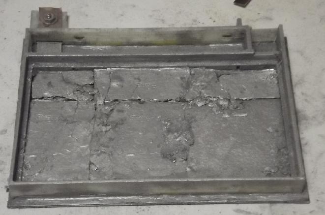 The zinc side of the flat cell,
made with
brittle 50x50mm compacted zinc "briquettes", some cut to fit.
The zinc side of the flat cell,
made with
brittle 50x50mm compacted zinc "briquettes", some cut to fit.
The doped parchment paper went right over these. The toluened
watercolor paper went over that and
over the plastic lip around the edge to prevent any connection between
the zinc and the other electrode.
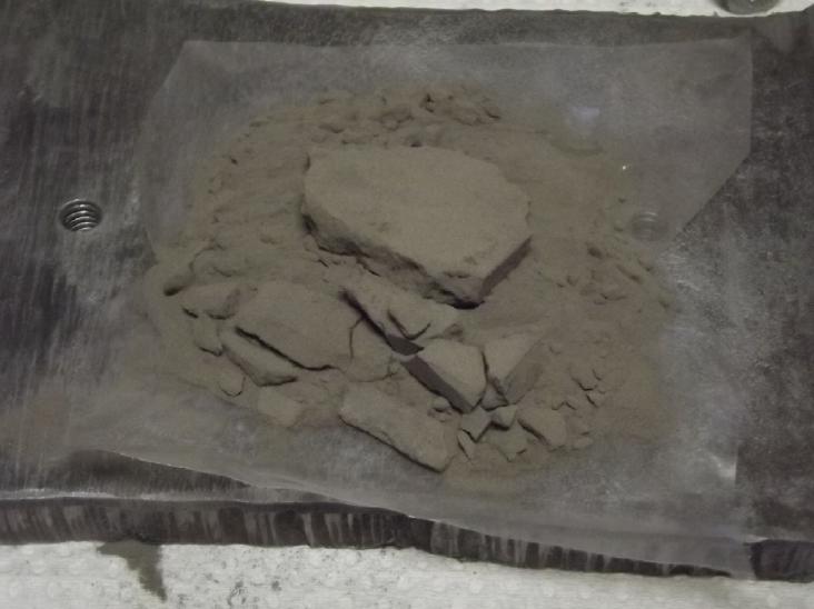 But when I
tried to compact monel powder (Ni:Cu 65:35?) into briquettes for the
plus side, they just crumbled and returned to powder. I ended up just
putting in Cu:Ni metal sheets. Simple. It's a prototype.
But when I
tried to compact monel powder (Ni:Cu 65:35?) into briquettes for the
plus side, they just crumbled and returned to powder. I ended up just
putting in Cu:Ni metal sheets. Simple. It's a prototype.
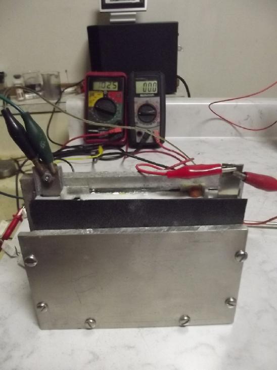 I
used a rubber gasket to close the front face. Even with just metal
sheets for electrodes it had much higher current drive than the tube
electrodes.
I
used a rubber gasket to close the front face. Even with just metal
sheets for electrodes it had much higher current drive than the tube
electrodes.
It ran very well at first but performance degraded with
cycling.
 I opened it
for inspection and trying things, and to clean the degrading CuNi
sheets several times, which brought the performance back up. Finally it
leaked like a sieve and I had to set
it at an angle in a tub of water to use it.
I opened it
for inspection and trying things, and to clean the degrading CuNi
sheets several times, which brought the performance back up. Finally it
leaked like a sieve and I had to set
it at an angle in a tub of water to use it.
By early January I figure
that monel is no doubt the best metal for the current collectors and
connection terminals. With the higher percentage of nickel it probably
won't degrade in use. And I expect that in the cupro-nickel as an
active electrode substance, while it was the initial spark to
considering copper electrodes, the nickel is superfluous. Simple copper
powder mixed with graphite to increase conductivity seems (so far) to
work great for active material and obviously has the highest energy
storage capacity. I'm determining that for sure in January's
experiments.
It would seem that when working well Cu-Zn cells may end
up
being rated as about 1.0 volts. Once it has been "conditioned" it will
recharge to over 1.15 volts with 1.25-1.35 volts supply. Moving two
electrons per reaction instead of one gives copper powder a lot of
amp-hours per kilogram and it is very dense. Even with the low voltage,
a small copper-zinc cell will pack a lot of energy both by weight and
by volume. 200-300 watt-hours per kilogram should be readily attainable
- higher than for nickel-zinc.
Such cheap batteries can improve off-grid energy
independence and provide hours or even days worth of electrical utility
level storage, making intermittent power sources more practical.
Assuming they can also provide high enough current capacities without
too much mass, they would also be great in EVs.
All battery chemistries and active materials have their
characteristics and peculiarities. Indefinitely rechargeable zinc is
novel and needs two special treatments to achieve, and rechargeable
copper hydroxide used at pH 12-13 is
essentially a brand new, untried material, so practical and optimum
ways to
employ it still need to be determined. But it holds incredible promise.
Turning that promise into working formulas and techniques will be the
subject of upcoming experimentation.
Salt electrolyte for rechargeable batteries, especially
making it a "moderately alkaline" pH 12-13, has been pretty much an
untried field. For most of the years while I've been trying to make
something
that works well in it, I've had more questions than answers and
unknowns (and "unknown unknowns") that held me back. The literature for
making alkaline cells is misleading or left them unanswered. This
winter and continuing
into January, answers or inspirations have been clicking into place.
Suddenly I have a new construction and an answer for a "nickel
manganates" chemistry I've
tried over and over without real success. Copper-zinc may be highest
energy density, but it not be the only cell type the coming months
development holds. ...if I can find the time for further explorations.
November and December have been much occupied with battery development
to the neglect of other things.
I'm trying a place in India for .3mm thick monel sheet
metal. (It looks like they might sell if I order a minimum order of 1
by 2 meters.) No luck - they said no.
Why Copper-Zinc Will Gradually Replace Lithium Types in many
applications
* First, the one notable downside to this chemistry is the low voltage:
there are more cells to interconnect for any given system voltage
The good features are, in principle:
* Very high energy density by weight and by volume
* High current capacity
* Large operating temperature range (at least at the high end...
probably from where the electrolyte freezes (-10?) to well over
+50°C.)
* Low cost (zinc and copper are cheap. Has some nickel, a bit of
zirconium & a microscopic trace of osmium. No cobalt, no lithium,
no rare earths.)
* Self balancing between like cells
* Safe to handle (KCl Salt electrolyte, pH 12 - not dangerously strong
acid or alkali)
* Safest in use - not prone to fire or explosion
* "Forever" long life (gelled electrodes last and last)
* Environmentally benign
* Easily recyclable
* Scalable from dry cell sizes to huge flooded cells
* No Patents. I have developed this chemistry and technology all by
myself without outside assistance or support over many months since
January 2008, and I hereby release all intellectual property has been
or may have been accrued in the process to the public domain. - Craig
Carmichael December 22nd, 2023.
Is all that together not "the best"? This is a battery chemistry and
technology that could be made as big wet cells or small dry
cells and used anywhere from power tools to EV's to off-grid to hours
or even days of on-grid energy storage. It can surely make intermittent
power sources for on-grid use much more practical than lithium types
do, and end the very occasional but intense and very dangerous
explosions and fires of large lithium cells.
Open Loop Air Heat
Pumping (OLAHP)
 Compressor
& G-code
Compressor
& G-code
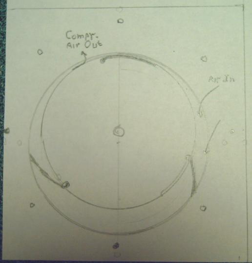
I came up with what must be about the simplest possible (&
hopefully most efficient) design for a rotary air compressor with
pivoting vanes. The rotor and the outside wall form two simple
non-concentric circles. The vanes scoop the air in and push it out the
output pipe, which of course will have a one-way flap to prevent the
air from coming back in. Centrifugal force opens the vanes and the air
pressure holds them open against the outer wall during compression.
I plan to make it with slippery UHMW body parts and alume
vanes. The tricky part will be having very fine clearances and seals to
prevent air escaping everywhere. It would seem that the vanes must be
flush with the rotor at the closed point, so they'll need thin
recesses in the rotor.
I did up a G-code file for routing out the rotor and outer
cylinder wall in one, with the diameter of the router bit (8mm) being
the average gap. So the widest point is 16mm where the air gets
trapped, and virtually nothing at the other side. The CNC router did a
dry run and it went as planned.
But I still need to figure out the G-code for the recesses
for the vanes, and I'm not sure how to do the hinge pins to let them
pivot without leaking air or falling out.
I may put together the rest of the system - the indoor
heat radiator and the indoor-outdoor heat exchanger - and initially try
them out with a refrigerator compressor. Maybe that can get a COP of 5
or 6 or better at freezing outdoor temperatures, and the more efficient
compressor-decompressor will be the upgrade after that.
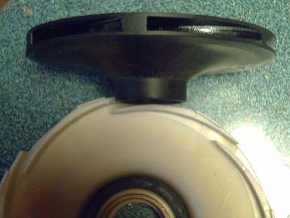 Decompressor
At the start of December I found a water pump impeller at the thrift
store. If I supported the center with a pen and blew into the top
center, the air came out the outside ends and it spun. It gave me the
idea to make a rotating expeller powered by the compressed air before
releasing it to the outdoors. As the air decompresses, it helps the
compressor to turn so the motor does less work to compress the new air.
This seems much the simplest way to make the rotary air
compressor into the compressor-decompressor wanted for OLAHP.
The decompressed air then goes through a wider pipe to
outdoors, through a hole in the house wall. At this point all possible
energy has been extracted from it and it is probably well below the
outdoor air temperature.
(There are probably going to have to be two or three glass jars in the
piping to accumulate condensation, which the user will have to empty
when they get too full. Knowing people including myself, that will
probably often be when the heater isn't working right any more.)
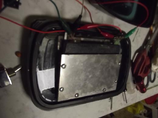
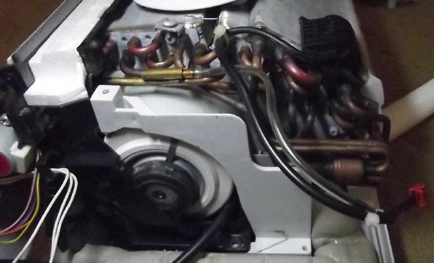
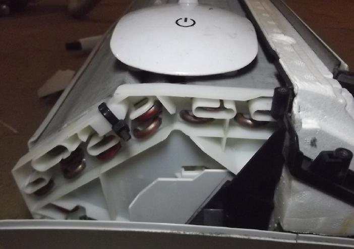
Indoor Heat Radiator
Perry gave me a "dead" wall mounted indoor heat radiator from a
refrigerant based heat pump. (Thanks Perry!) It had several very fine
radiators wrapped around a long "squirrel cage" blower fan. It is
apparent that any heat in the pipes will transfer very readily to the
tiny, closely spaced fins and be blown out of the unit by the fan. In
this way the radiating temperature is kept lowest - probably under
30°C, which helps to yield the best COP from the system.
 Heat Pump Indoor Radiator, cover
off.
Heat Pump Indoor Radiator, cover
off.
(I probably bent some of the "tinfoil" fragile fins myself when taking
it apart, moving it face down on the carpet.)
 At first I thought it would be ideal also for air, but the tubes pay no
attention to gravity and I suspect it will become a serious collector
of condensation and they will plug up with water. Nevertheless it
should radiate the heat from the compressed air admirably until then
and I will try it, and if necessary (and if I'm actually able to in the
cramped space) do some re-plumbing of its tiny tubes.
At first I thought it would be ideal also for air, but the tubes pay no
attention to gravity and I suspect it will become a serious collector
of condensation and they will plug up with water. Nevertheless it
should radiate the heat from the compressed air admirably until then
and I will try it, and if necessary (and if I'm actually able to in the
cramped space) do some re-plumbing of its tiny tubes.
A ready-made and well designed indoor heat radiator seems
much the best way to do one rather than making some inferior "DIY" unit
myself when I have no special ideas to try out for this aspect of the
system.
 The reason the
unit was "dead" was that its logic board had failed. The logic board
drove the fan motor with 340 VDC and a 12-15 V PWM logic signal,
seemingly at about 200 Hz. (I couldn't find datasheets on the motor
even with the manufacturer and model number - only on the whole heat
pump.) I decided to try rectifying 120 VAC to 170 VDC and seeing if it
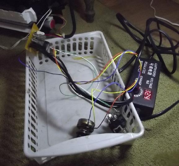
would run at the lower voltage. I had to make a circuit board with the
170V stuff, PWM and all. It uses a simple 555 timer to generate the
PWM, and a variable power adapter I had handy to make the 12V power.
The reason the
unit was "dead" was that its logic board had failed. The logic board
drove the fan motor with 340 VDC and a 12-15 V PWM logic signal,
seemingly at about 200 Hz. (I couldn't find datasheets on the motor
even with the manufacturer and model number - only on the whole heat
pump.) I decided to try rectifying 120 VAC to 170 VDC and seeing if it
would run at the lower voltage. I had to make a circuit board with the
170V stuff, PWM and all. It uses a simple 555 timer to generate the
PWM, and a variable power adapter I had handy to make the 12V power.
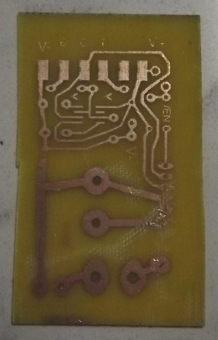
I used the "fingernail polish" technique to transfer laser
printer toner from glossy paper to the copper. The toner was too light
even printing the paper twice over and there were a couple of gaps in
the lines. At least the printer usually managed to put both prints in
exactly the same place!
 After making some mistakes
that cost hours of extra work, I got it working, all without shocking
or electrocuting myself. The fan buzzed at any intermediate speed. It
didn't seem too bad, but it got much louder when the unit was
reassembled. So it'll probably always be run at full fan speed
regardless of the speed control. Perhaps the original logic unit used
the "feedback" signal from the motor to know when to apply pulses to
avoid buzzing, or perhaps it just didn't buzz notably when run at 340
volts.
After making some mistakes
that cost hours of extra work, I got it working, all without shocking
or electrocuting myself. The fan buzzed at any intermediate speed. It
didn't seem too bad, but it got much louder when the unit was
reassembled. So it'll probably always be run at full fan speed
regardless of the speed control. Perhaps the original logic unit used
the "feedback" signal from the motor to know when to apply pulses to
avoid buzzing, or perhaps it just didn't buzz notably when run at 340
volts.
 It Runs!
In addition to the fan, there are a couple of electricly
operated louvers among other things such as a temperature sensor on one
of the tubes. I'll have to ignore these embellishments (at least for
now) and just be happy to have it essentially working.
Cabin Construction
Well, December was
mostly too cold and wet to want to go out and work on the cabin. But I
did get a few things done.
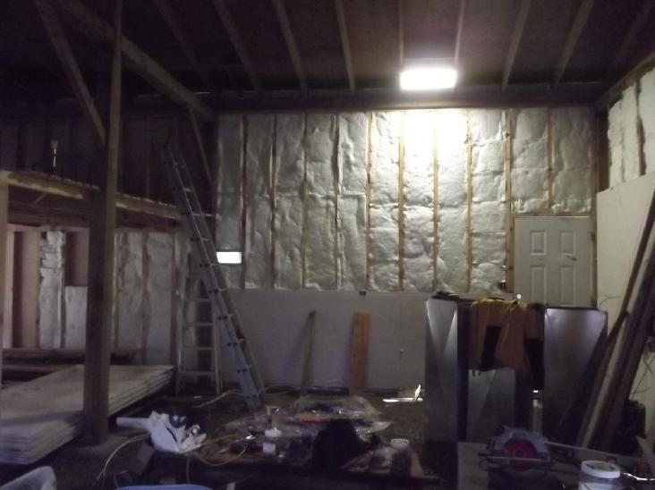 At the start of the month I had
the east side
of the north wall insulated.
At the start of the month I had
the east side
of the north wall insulated.
 Then I put up the gyproc, with
the light switch
and one 40VDC outlet
Then I put up the gyproc, with
the light switch
and one 40VDC outlet
box... and wires below it to trip over until the raised floor is made.
 [10th]
I got out another bag of R12-15 inch insulation and filled most of the
cavities in the north wall.
[10th]
I got out another bag of R12-15 inch insulation and filled most of the
cavities in the north wall.
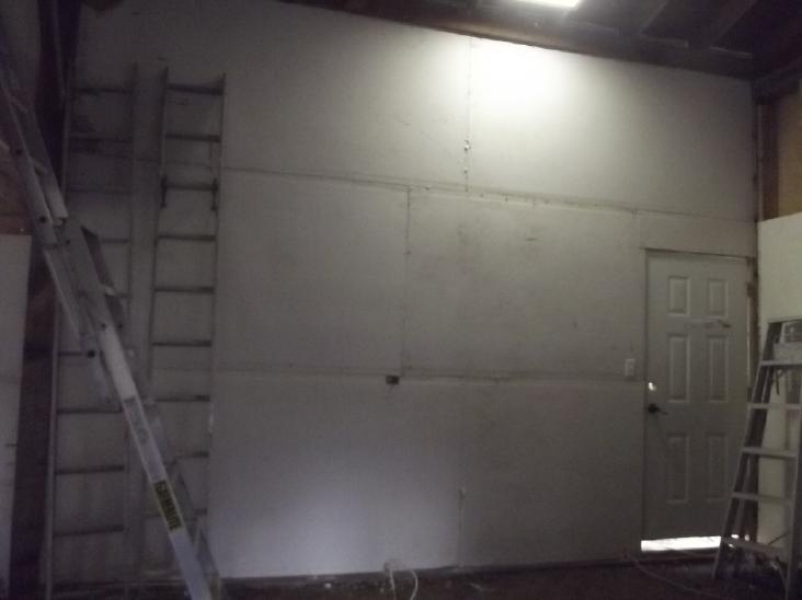
Sometime after that I put up the gyproc on the garage
north wall.
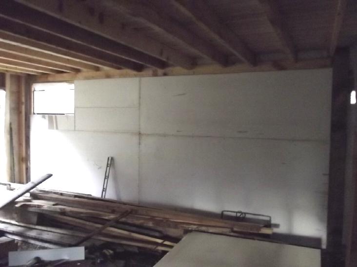
 Sometime I put up a sheet of gyproc on the upstairs wall, and
eliminated the pile by carrying off the last five sheets. The headroom
being so low, some scraps will finish to the floor.
Sometime I put up a sheet of gyproc on the upstairs wall, and
eliminated the pile by carrying off the last five sheets. The headroom
being so low, some scraps will finish to the floor.
I did a second session of
'big
gap filler' foam between the tops of the outside wall sheet metal
panels and
the plywood of the roof, where there was no wall plywood between the
rafters on the north and south walls and no way to connect everything.
Half the south wall remains. (It's really cluttered over there!)
Gardening
Not much happening except I've been letting the chickens
out for a half hour before dark. I figure the hawks have gone to bed
and the raccoons aren't out yet, and they scratch up and fertilize
garden patches. It's worked so far. But I'll have to keep them out of
the gardens come spring.
 A ripe coffee bean on one of my
three coffee
plants under LED lights!
A ripe coffee bean on one of my
three coffee
plants under LED lights!
 After I cut down the right hand
lettuce, I kept
watering the root and it has kept making leaves.
After I cut down the right hand
lettuce, I kept
watering the root and it has kept making leaves.
Winter lettuce all winter!
 It's probably time to toss the
"winter cherry
tomato", but it has produced a lot of little tomatos.
It's probably time to toss the
"winter cherry
tomato", but it has produced a lot of little tomatos.
(The latest ones are really tiny - it has probably used up most of the
nutrients in the pot's soil.)
 The second coffee plant has about
50 beans, but all still green.
The second coffee plant has about
50 beans, but all still green.
A pot of my own coffee still looks a long way away.
(The third one got "roasted" in my window greenhouse on a hot day and
is still recovering. No beans.)
In
Passing
(Miscellaneous topics, editorial comments & opinionated
rants)
Scattered
Thots
* How to turn polyethylene into clean heating fuel (LDPE, HDPE, UHMW -
grocery bags, milk bottles, dairy/margarine tubs saying HDPE, etc.):
(1) Throw the plastic into the woodstove with a fire lit.
Nothing more is required. The plastic melts and turns into
liquid fuel, then vaporizes and ignites. Same as liquid petroleum
fuels. The combustion products are
just water vapor and carbon dioxide. It's completely clean; there's no
residue or smoke. Polypropylene (PP) is generally similar. Many other
plastics aren't so clean to burn, but these, the most common single use
plastics, are. Why are they occupying landfill mountain ranges?
It burns hot - don't put in too much at once.
* Clothing/fabric to shield for tinnitus/power line radiations
I
found a store on line that specializes in mitigating the effects of
power line, RF and microwave radiation. (LessEMF.com) It seemed to be
the only one of its kind. They don't mention tinnitus - just
"irritation" or "aggravation" from AC power line fields, but they spoke
of the delayed effect like tinnitus, where you don't notice this right
away but
instead after some time, maybe with many hours or even days of
exposure. I ordered a tuque/beanie and a
pillowcase that are made in two layers, one containing conductive
silver threads. The pillowcase was for if you keep a cellphone under
your pillow (?!?) but I may just turn it with the inside layer out and
put it right over my head. (I would think it's important for shielding
that the conductive part doesn't conduct to You.) If the tuque doesn't
cover enough of my head, I just might be found walking around with a
pillowcase with eye holes in it over my head. (Nothing odd about that!)
They have gauss and electric field gradient meters too.
("up to 1000 volts/meter") But I didn't get one. As I've said, with the
14,400 V power lines about 10 meters up, I expect we can deduce that
that's 1,400 volts per meter underneath. (Their device would be
overloaded!)
* William Rees (on Youtube) had an interesting perspective on the role
of cities in
overshoot. "Overshoot" of the ecology's "carrying capacity" is using
annually more resources and producing more waste than are being
regenerated and reprocessed by nature - today "drawing down" resources
that will be
needed in the future. He likened cities to "the human
equivalent of animal feed lots" where the food comes in from outside
and little is produced within. He said Tokyo, as an example, in terms
of its present "ecological footprint", is twice the size of the
entirety of the Japanese islands. As long as resources can be imported
everything looks fine, but those imports may be "drawing down" the
resources of an area as much as 100 times as large as the city itself.
Rees says all our multitudinous environmental problems are
symptoms, symptoms of overshoot. We now draw down resources (even the
renewable ones) much faster than they are being replenished and emit
far more waste than the environment can absorb and process.
If this sounds like things I've said before, I got them
from thinking people like Rees and William Catton Jr, who are also in
accord with what has
been and is being channeled in recent decades from various spirit
beings - angels and other "celestials".
Eight billion people can't long go on living on a planet
that can only sustain around three billion. That the birth rate has
fallen so much since the availability of effective birth control is
very heartening for the future - we won't have to continue boom-bust
population cycles indefinitely. But in the meantime after decades of
overgrowth, decades of disasters are inevitable until the population
has fallen to levels still sustainable, which may be around or under
two billion for a while until a more healthy ecology has been restored
and the "drawn down" resources of nature replenished.
ESD
(Eccentric Silliness Department)
* What is it that makes tardigrades late?
* Which are more dangerous: manta rays or gamma rays?
"in depth
reports" for
each project are below. I hope they may be useful to anyone who wants
to get into a similar project, to glean ideas for how something
might be done, as well as things that might have been tried, or just
thought
of and not tried... and even of how not to do something - why
it didn't
work or proved impractical. Sometimes they set out inventive thoughts
almost as they occur - and are the actual organization and elaboration
in writing of those thoughts. They are thus partly a diary and are not
extensively proof-read for literary perfection, consistency,
completeness and elimination of duplications before
publication. I hope they may add to the body of wisdom for other
researchers and developers to help them find more productive paths and
avoid potential pitfalls and dead ends.
Electric
Transport
[No
Reports]
Other
"Green"
& Electric Equipment Projects
Air Compressor Designs
for Open Loop Heat Pumping ("OLAHP")
Simple Decompressor!
I
found a bag "FitsAll - pump replacement
parts" in the thrift shop. On some hunch I bought it. It turned out to
be a
"diffuser" and "impeller". Apparently the impeller with its curved
blades pulls water in from the periphery (where the diffuser helps aim
the water) and shoots it out the center, presumably into a pipe.
If I held it loosely and blew hard into the center, it
spun. What if, with a rotary compressor on the same shaft, the
cooled air to be decompressed was instead fed into the center of the
"impeller" and allowed to decompress out the curved fins? With an
"impeller" ("expeller"?) designed for air, the expanding air could help
spin the compressor's rotor, thus helping to compress incoming air. It
would add almost no friction to the system and so could only help. The
compressor section could focus on compression alone and have no more
pivoting vanes than needed for that.
Simpler and more efficient - now we're really getting
somewhere!
Instead of curved blades
for impelling water, perhaps one
for expelling air might be a couple of curved tubes with "rocket
nozzles" at the ends? The air has to be fed in from the center with a
rotating seal, so the configuration will have to be motor at one end,
compressor section next, then the expander with the air tube at the
other end. The center seal might perhaps be a sealed bearing with the
center and pipe connection holding the end in place, and the outside
spinning with the expander (and compressor).
Pivoting Vanes Rotary Compressor
The essentials of the pivoting
vanes rotary air
compressor,
with non-concentric rotor and outer cylinder
[20th] I hadn't worked with gcode and the CNC router in a long time.
Last I recalled I had finally got it all working and then didn't have a
6mm shank router bit, but that was the only shank size collet I had. I
had ordered bits and then moved on to other things. (Just as well since
I later changed the rotor design to a Hallbach configuration.) That was
a year ago. Now I wanted to cut UHMW plastic to make the rotary
compressor. I wrote up a gcode file to do some of what I wanted.
Luckily I guessed the name and password on the CNC
computer. I never wanted to require a name and password on a computer
that isn't even on line, but it forced me to make them. I couldn't
remember what name (really a second password) I had used; luckily it
was my first name. After a few hiccups, the program ran and the table
ran through the X Y Z motions, without me actually turning on the
router
and cutting anything.
I have a few more complex bits of curved shape to figure
out for the three vanes before trying to route; even more complex to
work out G-Code for them! (Also I might put air passages and the
one-way compressed air leaf in the outside of this center part rather
than in the top part that attaches above.)
Indoor (Wall Mount) Heat Radiator Unit
I decided to set up the system in the dining area again,
with whatever new components I came up with. It seemed to me the first
thing that needed setting up was the indoor radiator unit. The one that
Perry gave me with the blown control board needs the fan motor to run,
if nothing else, to circulate the warm air. So the first order of
business was to get that to work.
I got the model number of the motor. The first time I
looked (with a microscope lens at the milliscopic print) I thought
"MFD" would be followed by the date of manufacture. But the model
number was in fact "MFD-12TYAL". Great! Except when I went on line
there was no data on it. All I could find was that it was made by
Fujitsu, and all technical references were to the air conditioners it
was used in. I did have a schematic of the air conditioner, and it
showed the motor connections, but without explaining actual operation.
[18th] Perry phoned and asked how I was making out. He got me looking
at the schematic again. On the motor pinout it turned out that the "FG"
on the motor (frame ground?) was actually called "FB" (feedback?) on
the air conditioner's schematic and wasn't grounded. There was some
other sketchy info that enlarged on the pinout diagram on the motor:
1- Vm (red) - It's supposed to be 340VDC, but it seems to run good on
170VDC (120 VAC rectified & filtered).
(no pin)
2- Ground (black)
3- Vcc (white) - from schematic, 15V (12+V from 8 dry cells in holder
worked)
4- Vsp (yellow) - from schematic, 0 or 15V PWM
5- FB ("Feedback?" - blue) - From schematic & testing: ground
through 1KΩ resistor to turn fan on?
When I had all the above satisfied, it still just sat
there. PWM could be 0V or Vcc, and FB could be 0V or Vcc (through
resistors), all to no vail. Then (after unplugging) I disconnected the
PWM input from ground and touched the clip to Vcc, and suddenly the fan
pulsed from the 170 volts still stored in the filter capacitor. I
plugged it back in. With a couple of touches of PWM to Vcc and off
again, and a few momentary starts from that, it started up and ran full
speed. I still need to make up some little board to hold the components
& wiring before I electrocute myself with 170V, so I might as well
put in a 555 timer to generate (?)200 Hz PWM, and be able to adjust the
speed.
In the evening I looked on my iMac. Sure enough there was
a 555 timer PWM board I had done up in EAGLE PCB in 2014. I expanded it
for connections to the fan, with pins for an external On-Off switch
(ground "FB" to turn on) and an external potentiometer for fan speed. I
rummaged through a drawer and (wow!) found a tiny tube of SOIC 555
timers to match the board.
Then I looked in my chemicals and found nail polish
remover for a new way to transfer toner from glossy paper to the PCB
for etching, which I linked to in TE
News
#161. (I knew I had bought some when I heard of it! Evidently,
from the comments, acetone doesn't work.)
[19th] I tried
it out. I don't think it works any better than the heat
method, but it seems easier. On the third try I decided it was good
enough and etched the circuit board.
[23rd] I discovered that the 5 pin motor plug was a standard .1 inch
spacing header. Why not make it so the motor plugged in with its own
plug? instead of soldering the motor's wires to the board? Later I took
the original socket off the dead PCB and used that too, so it would be
impossible to plug in in backward or a pin over. Then I designed and
made a new board. A day or two later I mounted most of the parts on it.
[30th] I finished putting
everything together. I had quite a bit of
trouble with it - all my own mistakes: an error in the design, swapped
two components on the board, a short... It's a good thing I made it so
it could unplug from the motor as I had to unplug it and mess with the
board on the electronics bench several times. I finally got the PWM
working right after about 6(?) hours of slogging away at it first in
the morning and then at night.
The motor ran
great at maximum speed. It really blows up a
storm. How a "squirrel cage" fan with no end openings can suck air in
at one part of its rotation and blow it out so strongly at another part
is a mystery to me.
But the slower I turned it down, the worse. A buzz,
perhaps a beat frequency of the PWM with the motor operation, got worse
inversely with speed, and trying to start it at low speeds it would
suddenly pulse once and then stop a couple of seconds before repeating,
even tho it would run (buzzing away) at the same setting if it was
already running.
It's good enough for now, but the buzzing (or the full
speed fan) would be annoying after a while and I hate to think of
trying to improve it once the unit has been reassembled. Maybe I'll try
a couple of different capacitors to vary the pulse frequency first, in
case that might synchronize it better with whatever it expects from its
regular microcontroller. (It's about 200 Hz right now. Hmm, G sharp -
yes, it's about a 200-210 Hz buzz regardless of how fast the fan is
running.)
[31st] The next morning I tried just touching a couple of smaller
capacitors in parallel against the one on the board to lower the pitch
(careful near that 170 VDC!). It ran rougher at low speeds. I decided
it was the best I could do, and after all it wasn't as much nuisance
noise as the fan's air itself. Perhaps it's quieter if it's running at
its rated 340 volts DC instead of 170? I'm probably lucky it runs at
all! "FB" seemed to be an AC output signal, not an "enable", perhaps
telling the RPM of the fan. I didn't check it out.
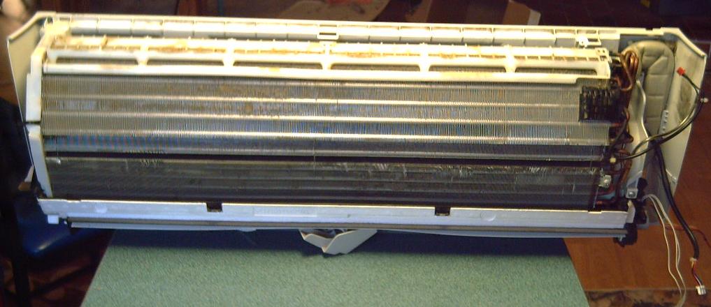
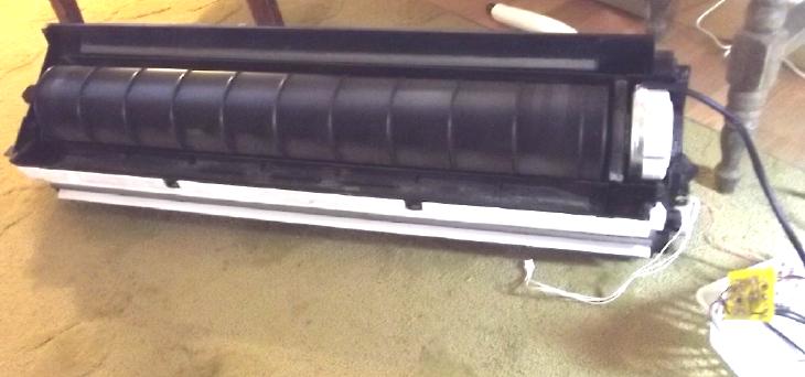
Radiator assembly reattached to
fan assembly
Next the board, power
adapter and speed control need to be
mounted somewhere and the unit reassembled, then I'll probably mount it
on the wall in the dining area somewhere. Then I'll make a better
indoor-outdoor heat exchanger, then hook up a fridge compressor and try
heating that room. Hopefully it will provide a COP or 5 or better at
freezing temperatures like that. Building the new air
compressor-decompressor will be the final piece to the puzzle to up the
COP.
It occurs to me that the heat exchanger should physicly be
indoors. Then any heat leakage warms the air being warmed anyway,
instead of cooling it. When I took the old one off the outside wall I
found a second reason - it wasn't weatherproof, the wind blew water
behind it, and it was pretty deteriorated after just 3-1/2 years out in
the weather.
Another lesson I learned in the disassembly: a fair bit of
water came out the end of a pipe. Condensation goes right along with
cooling air, and the pipes need to drain to the coolest point. There
there should be a transparent inspection bottle or something and a way
to drain the water out.
Two
dozen Condensation Traps!
I
trust the tubes in the indoor radiator are thin enough
to spit out the water uphill a bit into the next section. If they
don't, this indoor unit may not work for air. Or I'll have to mount it
on end with the entry and exit pipes down. Say!, that would probably be
best. Rats... on end the pipe loops would go up, down, and up and down
again, more than once - really deep water traps. That would be much
worse. If horizontal doesn't work, I'll have to change the
pipes so they all flow downward only and all end at a lowest point.
There would be up to around 8 loops of about 5mm pipes (out of 20 or
so) to take apart at the ends and re-plumb in parallel all ending at
the bottom - Yikes! (Disconnecting and doing a higher pressure "purge"
with an air compressor could be a temporary workaround, but would
become tedious quickly.)
Indoor-Outdoor Heat Exchanger
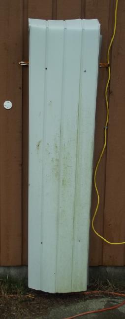
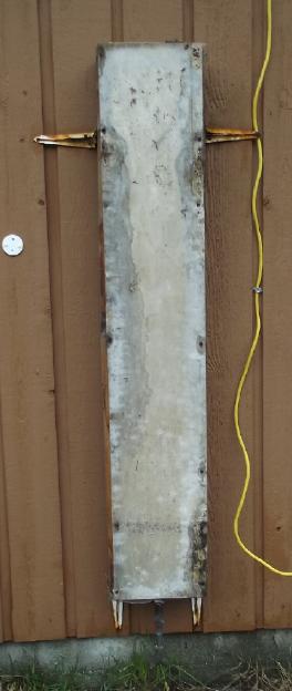 Having decided
the heat exchanger should be in the inside of the space, I removed the
one that has been attached to the outside wall since spring 2020. Water
was blowing in behind the metal cover and it was remarkably
deteriorated, with a wood bug colony inside. There's another great
reason for putting it indoors!
Having decided
the heat exchanger should be in the inside of the space, I removed the
one that has been attached to the outside wall since spring 2020. Water
was blowing in behind the metal cover and it was remarkably
deteriorated, with a wood bug colony inside. There's another great
reason for putting it indoors!
Cabin Construction & DC Wiring
Well, December was
mostly too cold and wet to want to go out and work on the cabin. But I
did get a few things done.
At the start of the month I had
the east side
of the north wall insulated.
Then I put up the gyproc, with
the light switch
and one 40VDC
outlet box... and wires below it to trip over until floor is installed.
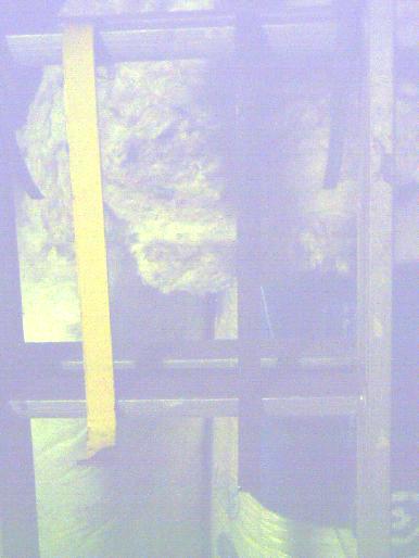 How to get those top sheets way
up there? I made
two hooks to hold gyproc on rungs on two ten foot ladder sections. By
alternately raising the left and the right sides I "walked" the gyproc
up the wall to get it to the top section. One could raise the left by
two rungs (left a rung higher) then the right by two (right a rung
higher), or to shift it horizontally while going up, one could raise
the left by one (left a rung higher), then the right by one (even
again), then the left again. Near the top I leaned four 2 by 4's
against it, two reaching near the top so it wouldn't tip and fall
forward, and two near the bottom so when it went into place above the
piece below it, the bottom wouldn't spring out again. No doubt it would
have been easier with two people.
How to get those top sheets way
up there? I made
two hooks to hold gyproc on rungs on two ten foot ladder sections. By
alternately raising the left and the right sides I "walked" the gyproc
up the wall to get it to the top section. One could raise the left by
two rungs (left a rung higher) then the right by two (right a rung
higher), or to shift it horizontally while going up, one could raise
the left by one (left a rung higher), then the right by one (even
again), then the left again. Near the top I leaned four 2 by 4's
against it, two reaching near the top so it wouldn't tip and fall
forward, and two near the bottom so when it went into place above the
piece below it, the bottom wouldn't spring out again. No doubt it would
have been easier with two people.
I didn't take a picture at the time. Here are the two hooks hung on one
ladder, only the yellow one being fairly visible in the darkness.
(The ends are "cupped" enough to hang on the ladder and to hold the
board
securely, and they're both really almost the same length. Honest!)
[10th] I got out another
bag of R12-15 inch insulation and filled most of the cavities in the
north wall. (Grr, need 4 more pieces... I'm reluctant to open another
bag to clutter up the floor right now. ...and, yikes, 80$/bag now!)
Sometime after that I put up the gyproc on the garage
north wall. (Fitting those little wall spaces between the rafters will
be a nuisance! But I don't want exposed fiberglass and I don't plan to
cover the garage ceiling.
[19th] I (finally) measured the north
half of the east wall for the
steel exterior face and took it into the building supply center for
them to bend and cut it. Assuming that goes well I'll do the other half.
Sometime I put
up a sheet of gyproc on the upstairs wall. I cut two more to fit but I
didn't want to open another bag of insulation yet, so I took up but
couldn't put in the sheets. (There's only 4 feet 8 inches of wallboard
height on the north side, so I can use scraps to finish the last 8
inches. There's a 6 inch beam above that for a total of 5 feet 2 inches
floor to ceiling at the edge, but this is the place where a few more
inches of headroom would have been really nice!)
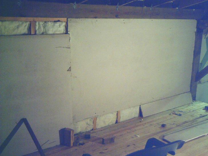
Storing this wallboard in the damp in a pile for a couple
of years has done it no favors as one can see from the cracks, rips in
the paper and discolorations. I'll trust a little filler and paint can
make amends. (I did save 120$ because the price has gone up since I
bought it. It's 33 $/sheet here now, virtually double the price on the
mainland. Anything heavy costs more, mostly because of shipping costs.)
Having whittled down the pile, I finally set the last
three sheets against a wall, opening up some floor space in the
cluttered structure. ...maybe even enough to lay out the garage door?
[26th] I did a second session of 'big
gap filler' foam between the tops of the outside sheet metal panels and
the plywood of the roof, where there was no wall plywood between the
rafters on the north and south walls and no way to connect everything.
I had done the north wall earlier except for the last space, and now I
finished that and did half the south wall. There the second can of foam
ran out. The first can that did most of the north wall (which was
previously used and quite old) still has some in it, but seemingly no
more propellant. Doing the wall as far as it went was excruciatingly
slow. Oh well, I have another can.
Spray foam was frustrating because it seemed if you used
part of a can it dried and the rest had to be discarded. But I looked
on youtube and found that one can clear out the "straw" with acetone or
nail polish for future use, as well as push (eg) a matchstick into the
nozzle and lay the can lid on top (else the foam will push it out).
(Note: They say to break off the tip so the match doesn't become a fuse
to ignite the highly flammable bottle!) When you want to use it again,
pull out the match and the dried foam comes with it.
Now I feel much more free to use some when it's
appropriate instead of wanting to wait until I had enough jobs to use a
whole can. By then I've forgotten what half the jobs were and they go
undone.
Electricity
Storage
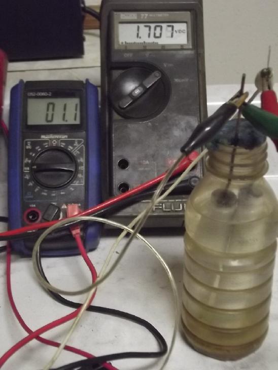
Everlasting Monel (Copper)-Zinc with Plastic Pocket Electrodes
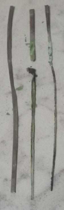 Left, cupro-nickel current
collector rod as
they went in.
Left, cupro-nickel current
collector rod as
they went in.
The other two are how they came out after 3 days of charging
at 2.1 volts, corroded entirely away at the water line.
 The
cupro-nickel metal corroding away in the new
perforated tube
electrodes seemed to explain some problems I had been having. Why did I
think it was working? Apparently as previous battery makers had
discovered, graphite was the only thing that could be used for
positrode current collectors in salt solution. There may be something
else, but I haven't found it. Even gold might be marginal for oxidation
voltage, so it would have to be something like alume or titanium, which
form a one molecule protective oxide layer in air, but something which
works in
salt solution at pH 12 instead. Pure nickel does it at pH 14, but not
at lower pH'es. (Hence the popularity of strong alkaline battery
chemistries.) [Later: It works!... at a lower voltage!... and for that
reason.]
The
cupro-nickel metal corroding away in the new
perforated tube
electrodes seemed to explain some problems I had been having. Why did I
think it was working? Apparently as previous battery makers had
discovered, graphite was the only thing that could be used for
positrode current collectors in salt solution. There may be something
else, but I haven't found it. Even gold might be marginal for oxidation
voltage, so it would have to be something like alume or titanium, which
form a one molecule protective oxide layer in air, but something which
works in
salt solution at pH 12 instead. Pure nickel does it at pH 14, but not
at lower pH'es. (Hence the popularity of strong alkaline battery
chemistries.) [Later: It works!... at a lower voltage!... and for that
reason.]
[7th] With graphite rods inserted, the
tube electrodes were working and
held over 2 volts, but they were so poorly conductive they would take
weeks to charge and had extreme voltage drop and loss under load. I
weighed the rest of my "Ovonics" nickel oxide solution as 28.35 grams
and added 1.00 grams of "conductive carbon black" (herein "CCB") powder
- 3.4%. That doesn't sound like much but it's so light and fluffy it
looked more like 30+% by volume. Graphite powder is fairly similar.
I sharpened a 1/4" carbon rod on a belt sander into a cone
to stab into the electrode. I filled the electrode loosely with powder
and stabbed. It went all the way to the bottom with some resistance
near the end. I pulled it out and refilled the hole it made, then did
it again. It was now hard to put in, but the top half wasn't well
compacted. I tried it again with the last tube, stuffing more and more
around the rod and pressing it in with a thin stir stick, and did
better.
But the results weren't very good. The cell now charged
easily to the 2.1 volts of the power supply. Too easily. Soon it was
only drawing 5mA. At that rate it would take a month to charge! Driving
a load it was once again dying by the second and would only stay above
1.5V into a 50Ω load for somewhat over a minute. Charging overnight
didn't seem to help. In fact, the voltage dropped even faster under
load. But holding over 2 volts was promising.
It occurred to me to try soaking the mix in acetone with
the CCB in it. I tried an experiment of wetting one end of a "Q-tip"
with acetone and rubbing it on a sheet of "flex graphite" gasket. The
swab gradually picked up some graphite and became gray. There was
nothing seemingly taken from the sheet. Then I rubbed another spot with
the dry end. It made the graphite shiny but the swab remained white. So
it would seem acetone does dissolve graphite, even if only slightly.
I didn't have much nickel mix left so I just poured some
acetone into the jar and wetted it all. Then I had to wait for it to
evaporate, and in the meantime, I figured out from what had been
happening, something a little outside the box, and left the nickel.
Copper?!?
A year ago [TE News #176] I briefly noted that a copper oxide electrode
was
probably worth a try. The voltage was low but it's dense and it would
probably
move two electrons per reaction instead of one. But I didn't get to it.
Probably too bad. Here I am many months (but not years!) later.
 [9th] It seemed likely that
the excellent performance I was getting last month, except at only 1.3
volts instead of maybe 1.8 volts, was owing to copper reactions in the
cupro-nickel, of course coupled with
the zinc. According to the Pourbaix diagrams zinc and copper shouldn't
have been above 1.2 volts, more likely 0.95, but if it wasn't the
copper what was it?
[9th] It seemed likely that
the excellent performance I was getting last month, except at only 1.3
volts instead of maybe 1.8 volts, was owing to copper reactions in the
cupro-nickel, of course coupled with
the zinc. According to the Pourbaix diagrams zinc and copper shouldn't
have been above 1.2 volts, more likely 0.95, but if it wasn't the
copper what was it?
(BTW the zinc should be much less soluble at pH 12 than at pH 14.
That's hopefully unimportant with the gelled electrode, but it
can't hurt!)
 With the zinc
presumably reacting at about -1.2 volts, If I had charged the cell at
1.4 to 1.6 volts instead of 2.1, the nickel component would have stayed
well under the +.6V where it oxidizes. So it might (should) have
remained in metallic form [that thought was not correct as such, but
read on]
and if so would have
been a good current
conductor for copper - that has to beat graphite!
With the zinc
presumably reacting at about -1.2 volts, If I had charged the cell at
1.4 to 1.6 volts instead of 2.1, the nickel component would have stayed
well under the +.6V where it oxidizes. So it might (should) have
remained in metallic form [that thought was not correct as such, but
read on]
and if so would have
been a good current
conductor for copper - that has to beat graphite!
Finally! A metallic current conductor for a positive
electrode in salt solution! Obtained by using a lower voltage active
electrode metal.
 The copper
should have oxidized at what would seem by the pourbaix diagrams to be
around 1.0 cell volts but which appeared in this experimental case to
have
been
about 1.3. The discrepancy was such that at first I didn't think the
reactant could be the copper.
The copper
should have oxidized at what would seem by the pourbaix diagrams to be
around 1.0 cell volts but which appeared in this experimental case to
have
been
about 1.3. The discrepancy was such that at first I didn't think the
reactant could be the copper.
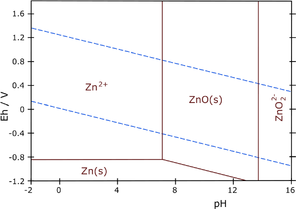
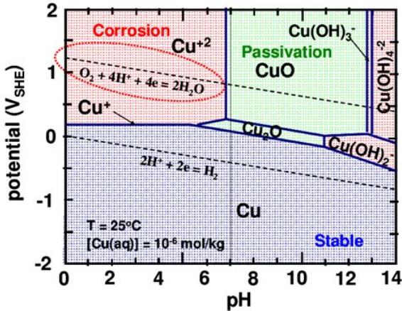
Whether copper as Cu (metal) <=> Cu2O, and or Cu2O
<=> CuO, would make good batteries at pH 12 in KCl salt depends
on which Pourbaix diagram one looks at.
This first one indicates a voltage a little below zero and the
production of a soluble ion [Cu(OH)2-], which would probably give it
short life. Long ago looking at this, and at some reactions in a list
that
mostly
showed dissolved ion results, I thought copper would most likely
dissolve away and (with no one else using it either) I didn't bother
trying it.
(On reading 'history' in Alkaline Storage Batteries, it seems
people did try copper early on. But it was definitely too soluble at pH
14, and
the voltage of copper-zinc at that pH was only .85V. Some earlier
copper-zinc cells in strange electrolytes at lower pH were 1.1 volts.
But none were made to be rechargeable.)
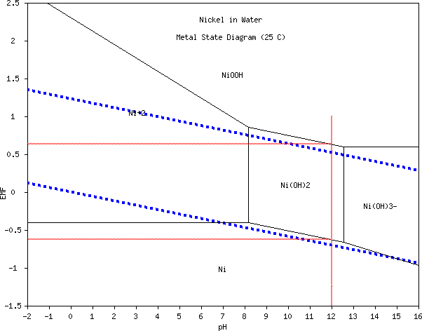
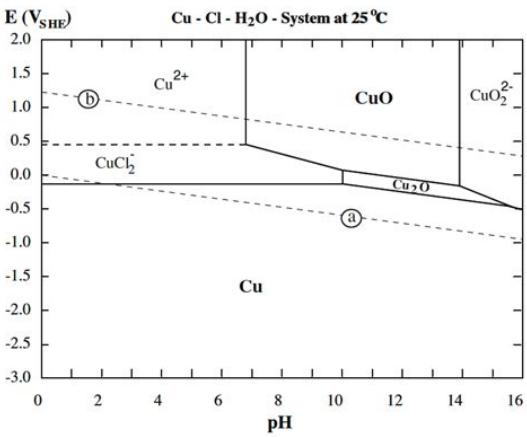 The
second one, which does indicate chloride salt electrolyte (seeing "CuCl2-"),
looks
much
more
promising.
It shows only solid reactants around pH 12. A second
wild card besides solubility is the CuO. The voltage to charge to CuO
isn't much higher than for Cu2O, and the upper diagram says
"Passivation", which I assumed meant it's a non-conductor and hence
won't discharge. But now I see another diagram that says "passivation"
for ZnO, which
is clearly not the case. (I guess the term is applied as opposed to
"corrosion", not in the sense of inactivating a battery cell.) On line
it seems neither form is an insulator.
The
second one, which does indicate chloride salt electrolyte (seeing "CuCl2-"),
looks
much
more
promising.
It shows only solid reactants around pH 12. A second
wild card besides solubility is the CuO. The voltage to charge to CuO
isn't much higher than for Cu2O, and the upper diagram says
"Passivation", which I assumed meant it's a non-conductor and hence
won't discharge. But now I see another diagram that says "passivation"
for ZnO, which
is clearly not the case. (I guess the term is applied as opposed to
"corrosion", not in the sense of inactivating a battery cell.) On line
it seems neither form is an insulator.
If the voltage of CuO-Zn is the unexpectedly high 1.3
volts
as seen in the
actual cell, and if the substances formed are all solid per
the second diagram, and if CuO in chloride at pH 12 doesn't
"passivate", then each copper atom could move two electrons just like
the zinc, and a copper-zinc cell should have a lot of energy by weight.
(Copper by itself would in that case be 843 mAH/g and the current
collector could
(presumably) be nickel. CuO would be 673 and if Cu(OH)2 is formed
instead, that would be 560 mAH/g. Then, if only one electron is moved,
eg Cu <=> Cu2O, or Cu2O <=> CuO, the figures would be
halfed, taking it to 336 or 280. Much also depends on what portion of
the theoretical value is actually attainable.)
And I've already made it work except I was charging at too high a
voltage.
A difference from the Zn
=> ZnO reaction is the voltage difference of the two copper
reactions: .2 volts. It may be that the cell will be 1.3 volts fully
charged (CuO => Cu2O) but drop to 1.1 volts at half charge (Cu2O
=> Cu metal). This is probably bearable if everything else is
excellent.
If the copper is 843 mAH/g and the zinc is 820 mAH/g and
both move two electrons,
about the same amount of metal would be required by both electrodes. If
both reactants are well utilized the potential would seem to be there
to obtain 200 or even 300 mAH/g in an actual cell? If we called
"nominal" cell voltage 1.1V, 300mAH/g would be 330 mWH/g. 220 is
fantastic... 330 beats most other types!
Imagine that: back to two of Volta's original
"electric pile" metals, both cheap and common!
WHY AM I BOTHERING WITH NICKEL?
A number of earlier experimenters had made copper-zinc
cells, But no one had made one that was rechargeable before. At
neutral pH and at pH14 copper and perhaps both metals were too soluble.
And at pH 14 the
cell voltage was said to be just .85V, where it was 1.1V in salt. What
did I have that they didn't? (1) I had pH 12 electrolyte. (2) I had
cupro-nickel or monel alloy. (3) I had (I believe) tamed the zinc side
with the soap gel.
I stuffed a few slivers of cupro-nickel into one of the
tubes and put it alone with the zinc electrode into the cell. I set the
charge at 1.6 volts. In a while it was charging at over 50mA, 1.57V. It
drove a 50Ω load at 1.2V or 20Ω at 1.1V, and it only dropped millivolt
by millivolt over the seconds, unlike the rapid drops I was getting
from nickel electrodes. Being driven down it recovered quickly to
1.26V. All just from those few little slivers of cupro-nickel, charged
for only 20 minutes or so! How about with a real, fully charged
electrode? After a little more charging short circuit
current was 360mA, with no fade over several seconds.
It's simple! It's fabulous! Cu-Zn it is! How did I miss this? How has
EVERYBODY missed this? Probably because of concentrating on pH 14,
where its voltage is so low?
Inventory... Let's see...
* I have a big amount of 70:30 cupro-nickel sheet. Assuming that's
enough nickel to hold it together when the copper is charged, great.
* I have quite a lot of sheets of nickel-brass, IIRC Cu:Ni:Zn 65:17:18.
Is that enough nickel to hold when the Cu & Zn are oxidized? Maybe.
(The Zn in this case is useless.)
* I have a can of fine monel powder from AEE. (Cu:Ni 60:40?) That
should make a great additive.
* And I have a big chunk of monel (somewhere) and a grinder to make
more powder if
necessary.
Monel comes in multiple flavors, and I don't have specs on
mine. It seems typical monel is only around 1/3 copper. This is a bit
disappointing copper reactions- energy density-wise, but it may make it
the most stable compound.
(Hmm... In 70:30 cupro-nickel, 30% nickel reduces the figure to
558 mAH/g. And monel is less than 50% copper, making it below 400.
Nickel-brass is about 65% copper for 518. But will the ones with more
copper hold together under charge and discharge as the copper oxidizes
and reduces? I guess the best alloy proportions will have to be
determined.)
[10th] I printed a couple more porous PVB tubes. The printer stopped
printing on the first one. It came out badly and I had to glue it back
together at one layer with methylene chloride, so I did the second one.
I put a toluened watercolor paper in, then put in some monel powder and
a cupro-nickel strip for a current collector. There were no additives
to the copper except the nickel it was alloyed with.
Tube + cap + paper - 4.95 g
CuNi strip - 3.90 g
Monel - 27.25 g
Total Cu:Ni - 31.15 g
Estimated copper content - 13 g (?)
Theoretical capacity: 843 mAH/g * 13 g = 10361 mAH. (10 amp-hours)
From last month, the zinc tube's theoretical capacity is also 10 or 11
amp-hours. Considering that (at 300 mAH/g of much lower density
material) several nickel oxyhydroxide tubes need to be used to match
the one zinc tube, this makes for an amazingly compact cell.
Total tube weight - 36.20 g
Zinc tube total - ~~23 g
Total both electrodes - 59 g
10 AH / .059 Kg = 169 AH/Kg
@ 1.1 volt = 186 WH/Kg
Other than the excess bottle of liquid electrolyte they're sitting in,
this is
already in league with good lithium cells. And that's with half the
copper electrode substance being nickel current conductor, plastic tube
electrodes adding to the weight and no particular attempt to make it
lightweight.
The tube fell over on the bench and monel powder came out
the side, from top to bottom. The art paper and the monel were of
course dry. But, wow, what fine powder to come right through the paper!
What had worked for nickel hydroxide didn't seem to work for monel.
I put the tube in the cell. (The saving graces are that it
might not come through once the paper is wet, and the tube electrodes
can be physicly separated to prevent shorts.)
Being in metallic form, all the copper was totally
discharged. The cell started at about 1.15 volts, but when I connected
the charge it just shot up to the power supply voltage drawing only a
milliamp of current. I noticed a glug ------- glug ------ glug sound
and realized that the paper and monel had to soak up the
electrolyte. So I left it sitting.
After 40 minutes I tried again. 2 milliamps. I suspect the
copper needs to oxidize some before it really starts to charge. The
zinc is probably mostly charged. I hope it doesn't bubble up too much
hydrogen and all turn into useless zinc hydride while the plus side
charges!
[11th] I tried a couple of load tests. They didn't run very long -
disappointing! I looked for that "step" voltage in discharge, where
reactions would change from CuO=>Cu2O to Cu2O=>Cu metal, but I
didn't see it. With a 50Ω load it ran pretty smoothly down from 1.17 V
down to 1.10 V, then faster and faster until below 1.0 V it was
dropping like a rock. .7 V to .6 V went by in a flash and I stopped it.
(Some time I started a load test and gor distracted... when I came back
it was still going, at about .4 volts. I immediately shut it off. I
should have let it run longer and seen whether that voltage was
dropping fast of stable. Ni(OH)2 => Ni (metal) seems like a likely
candidate for producing about that voltage with Zn => ZnO.)
I started looking up more details about copper compounds.
What is the difference between Cu2O & CuOH, and between CuO [black]
& Cu(OH)2 [bluegreen]? Which ones are actually formed in the cell?
(It seems to me cupro-nickel sheets have usually turned blue-green,
although that could be from the nickel.) Evidently the
valence one compounds are pretty unstable and soon go to valence 2 or
0. No step voltage. So the actual half reaction is probably, in effect:
Cu(OH)2 + 2 e- <=> Cu (metal) + 2 OH- , @ ~ +.1 volt
( or else CuO + 2 e- + H2O <=> Cu (metal) + 2 OH- )
Initially poor currents improved in spite of the
exceptionally low charge rate. Once charged to a certain level and then
discharged it would regain the charge to that point rapidly before it
dropped to unit milliamps again. So while the initial charge was taking
'forever', subsequent charging went at a good rate. I made a little
table, but I didn't take it farther before trying other things.
Time
|
Short circuit
current (mA)
|
Initial charge
current (mA)
|
Run 50Ω load
time (minutes)
|
10th PM - not
long after making
|
140
|
40
|
|
10th evening
|
180
|
50
|
|
11th AM
|
260
|
60
|
15
|
11th PM
|
300
|
80
|
|
11th Eve
|
360
|
100
|
|
12th AM
|
300
|
90
|
30
|
On the evening of the 12th after 3 days of promising testing I suddenly
thought, "Where is my head?!?" The transition from nickel hydroxide to
nickel oxyhydroxide is at +.6 volts, but the transition from nickel
metal to nickel hydroxide is at -.6 volts (~ pH 12). Why would I think
that the nickel component of the cupro-nickel wouldn't oxidize away
when, even before, the copper oxidizes?
I opened the cell and pulled the cupro-nickel strip out of
the electrode. Rather to my surprise now it still seemed solid. It was
black on the surface with copper or nickel oxide, but it was solid. And
the black didn't seem to wash off readily when wiped. Nor was it
thinning at the water line. It looked like the same width as when I put
it in and calipers said it was no thinner.
There must be something in
the combo that it doesn't oxidize like either metal alone would - at
copper reaction voltages. The surface oxidizes, but the oxide layer is
solid and protects the interior - just like alume or titanium in air at
pH 7. Would this happy state continue indefinitely? If so, it is after
all a "metal that doesn't oxidize" at copper reaction voltages and pH
12. Maybe in my mental confusion I've found that this alloy was just
what I was hoping to find.
{[Written later, 20th]
Come to think of it, monel is known
for its anti-corrosion property in salt water. It was used widely in
marine applications before the creation of stainless steel. That must
be why! In the battery cell the positive voltage enhances propensity to
oxidize. Now to initially charge a cupro-nickel/monel electrode, the
nickel at the surface must first convert to nickel hydroxide, almost
spontaneously (-.6V). Then nearer to zero volts, the surface copper
must convert to cuprous hydroxide ( CuOH ), then at +.2 volts to cupric
( Cu(OH)2 ). Usually there's no "+.2V" in sea water. So, oxide comes
off
(orange sludge) but when it reaches a certain surface composition, a
certain proportion of nickel to copper oxides, and if it isn't further
oxidized to nickel oxyhydroxide (by raising charge voltage so the monel
hits +.6V), this mixed oxide must stay on the surface, preventing
corrosion of the interior of the metal. Hence the terminal strips not
being eaten away. In the fine monel powder, the surface area is large
for a small interior, giving a lot of active material.
[And, 26th] An alloy is a mixture of any metals. Two
metals as close in atomic weight and number as nickel (#28) and copper
(#29), intimately mixed at the molecular level and which form the same
crystalline structures are also said to be in "solid solution".
Compounds of those metals (such as oxides) can also be in "solid
solution". Thus oxidized monel and cupro-nickels may be said to be
solid solutions of nickel-copper oxides.
[28th] There may also be combination compounds involved
depending on whether oxides or hydroxides are formed and varying with
state of charge/oxidation, esp. considering the top copper pourbaix
diagram showing copper ions, for example: Ni(Cu(OH2))2, Ni(Cu(OH)3)2
[or Ni(CuOOH)2] and other mind boggling possibilities. These may
perhaps provide varying voltages and electron movements as well as
stability of crystalline forms, and hopefully considerable
stoichiometry with charge and discharge. Note that the third
hypothetical form is just the first with a hydrogen expelled from each
Cu to raise its valence state, similar to how nickel hydroxide (II)
charges to oxyhydroxide (III): Ni(OH)2 [AKA NiOHOH}=> NiOOH.
}
Regardless I stuck a graphite rod into the electrode and
put it back in the cell. Charging current stayed up around 25mA instead
of dropping off to almost nothing. But it didn't drive a load as well.
Short circuit current was 150mA instead of 300+ and voltage was lower
with a 50Ω load. But then I had only managed to plunge the rod 3/8 of
the way down.
I took the original cupro-nickel strip and put another
beside it, cut the slit wider in the cap, and to my surprise was able
to push them both most of the way into the monel powder. I tried that
and got higher currents that didn't drop to nothing way too soon.
Apparently the original strip wasn't making very good contact with the
powder. (What can one say when the metal powder won't compact notably
and then falls out right through the treated art paper?) Not sure that
was the limit I stuck in a third strip. Currents went up a bit more.
Now it was charging at around 50mA, for quite a while instead of just a
minute or two. Way better! The cell soon started holding higher
voltages, in fact over 1.2 volts instead of 1.15 for a 50Ω load.
[13th] After charging all night performance sucked. Voltages were down
and a short circuit made 140mA instead of over 300. After a while it
occurred to me to check pH. Voltages of copper-zinc at pH 14 are known
to be lower - said to be about .85V. It was down to 8. Of course! In
all my previous cells there had been some calcium hydroxide, but this
one just had the monel and cupro-nickel. 8 was low enough to start
dissolving the nickel and copper oxides. I dumped in a few grams of
CaO. That quickly brought it up to 12. (Even the previous cell where I
stuck a few strips of cupro-nickel into the previous nickel hydroxide
mix had CaO in that mix.)
In a while (time for the pH 12 to soak into the
electrodes) there wasn't any notable improvement. Then I pulled the
cupro-nickel strips out a bit and pushed them in again. That did it!
Voltages under load rose by 100mV to almost where they were the
previous day. Short circuit current rose to 270mA. I presume I rubbed
off some insulative oxide that formed in the pH 8. [Turns out to form
anyway. Monel sheet metal with more nickel than copper is surely
better.]
I'm pretty sure this is a good cell chemistry. But
performance still wasn't as good as the previous day. The fact that I
could push the strips in said to me the powder wasn't compacted enough
for good conductivity of oxides. Well, it wasn't quite full to the cap
now, with whatever had leaked out through the paper. What could I use
that wouldn't let that fine metal powder through? I emptied the tube
and put in parchment paper, shiny side in. (Wait... shiny side? It's
not plasticized is it?) [I should have looked... it was "plastic coated
freezer paper!"]
It seemed because of this it was starting all over again:
miniscule charging currents, low voltages under load. Worse than ever!
It was in fact doing better when I had just stuck a few bits of
cupro-nickel strips into a tube of nickel hydroxide powder. And it did
better if I filled the cell until the bottom end of the terminal was
immersed. As if the part of the stem immersed in the powder was hardly
counting. But only the powder was going to have enough surface area to
make the intended amp-hours.
[14th] By the next morning it was only slightly better. Maybe it just
needs a long, long time to initially form up? Maybe I should just leave
it on that itty bitty 2-5mA of charge and check in a week or two, and
go do other things? Or, what?
Later in the day it was no better, if not worse. I raised
the charge voltage to 1.8V. 1.4 to 1.6V seemed about right, but at 1.8
it still didn't draw much current: 10mA instead of 5. I don't want to
start making NiOOH and dissolving the terminal strip, but it seems to
need something to get it going. I decided to leave it there for a few
hours.
I moved the electrode around in the bottle by moving the
terminal. The position made a tremendous difference to performance.
Especially, how much of the cupro-nickel terminal strip was immersed. I
filled the bottle a little fuller and it was up to the best performance
it had given.
[15th] Performance was crap again. A 50Ω load was well under .9V. All
along I had noticed lightweight yellowish stuff coming out of the
electrode. It drifted slowly down and settled to the bottom of the jar.
At first there was just a bit. There was much more now, maybe because I
had upped the charge voltage. I had eventually decided it looked like
hydrated iron oxide. Monel can be 1% iron. Perhaps the cupro-nickel
wasn't so pure either? I shook the electrode and a bunch floated off
the terminal strip and even more out the slit in the cap, which had a
gap beside the terminal. Performance rose: 50Ω now gave 1.15V! Every
time I disturbed the electrode more came out the top. I shook it a few
more times, more came out, and the charge current went from 40mA to as
high as 115 and stayed higher. 50Ω started going over 1.2V. The water
became cloudy and the layer of yellow on the bottom got quite thick. If
I hadn't done the separate tube electrodes I'd never have figured this
out! I've noticed a bit of yellow ***t before and probably it's been
one one of my problems all along.
The coating of the electrode's active surfaces with
something that insulates and evidently prevents contact with the
electrolyte seems to explain the perplexing variableness in performance.
I was hoping it was a metallic impurity that was being
charged and washed out, but there seems to be far too much of that. It
must be either copper oxide or nickel oxide. Cu(OH)2 is black, but
Wikipedia says CuOH is unstable, but is yellow, so that's what it must
be. How can this work if the copper substance, even if not "dissolved"
per se, floats out of the electrode mix and drifts to the bottom of the
cell? I'm confused as usual.
Perhaps the secret is in the combo. On line I found [very
few and obscure] references to NiCuOx , CuNiOx
and similar. Since the voltage is under 1.3 volts, I'd hazard a guess
of NiCuOx, probably hydrated as NiCuOH and NiCu(OH)2
or NiCuO.
I decided to clean out all the yellow goop from the
electrode, seeing it kept coming and coming out the cap. It finally
managed to get all the bits of paper and the yellow stuff out and had
some monel [or whatever] left over - not nearly enough to fill the tube.
Then I went to get some more parchment paper... wait! The
box that I'm sure I must have used said "plastic coated freezer paper"!
(I was sure it said "parchment paper" when I used it!) Impervious! That
would explain a lot.
When I refilled the tube - just over half full - it
weighed 33.00g. An empty tube with a similat CuNi strip was 6.60g, so
the amount of monel (or whatever it had become) was 26.4g. I tamped the
powder down with a thin file and put it back in the cell, then set it
on charge. It did the same thing. More yellow smudge. Poor performance.
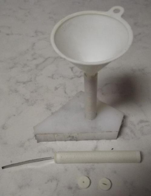 Setup to fill a "porous" plastic
electrode tube
with powder.
Setup to fill a "porous" plastic
electrode tube
with powder.
Nickel Oxyhydroxide Electrode
Frustrated, I got out the untried Ovonics mix with the
carbon black all acetoned in and printed a new electrode tube. I filled
it and stuck in a graphite spear for a current collector/terminal. Then
I pressed the substance down with a small copper pipe that fit over the
rod but inside the paper in the tube. It weighed 18 grams and had a bit
over 6 grams of the powder in it. (Wow, so lightweight compared to
copper!)
I filled a new bottle with 10% potassium chloride and put
in the new electrode along with the zinc one, abandoning the
cupro-nickel cell for the moment. I set the charge to 2.1 volts. The
cell voltage jumped right up to 2.1 and it started charging with the
same maddeningly low currents as the other cell. Was it the zinc side
that was to blame for those!?! Why had that simply never, ever occurred
to me? Of course, the zinc electrode was made with zinc powders and a
hydrogen overvoltage raising additive. So it was fully charged and
neither going to accept charge nor bubble hydrogen at any reasonable
voltage. There was nothing to complete the reaction to charge the
positive side.
A solid platinum electrode would bubble hydrogen without
itself being damaged. Hah! I knew I bought a piece for a reason! I
found it and put it in, removing the zinc "real" electrode. I turned it
up to 2.6 volts. Soon the Pt was bubbling merrily away with very fine
bubbles and the cell (the nickel hydroxide side) was charging at 20mA.
Not much, but it's a small piece of Pt and a lot better than 2 to 5mA.
Might I actually see some positive results for once? I left it charging
overnight - something like 200 mAH of charge, in an electrode capable
of holding 1800? But it's charge!
[16th] I put the zinc electrode back in. The cell held over 2.1 volts
for over 20 minutes. That's a definite improvement. Then I tried a 50Ω
load and the voltage dropped like a rock. It recovered to over 2 volts,
but it took 30(?) seconds after running the load for (?)5 and dropping
below 1.3V. In case the problem was the zinc side I stuck in a strip of
zinc instead. Same thing. Perhaps to get good current the nickel side
needed those tons of compaction pressure that Edison first noted, not
just pressing by hand? How far could I go without bursting the flimsy
porous plastic tubes? How do they make them work in big flooded
'prismatic' cells? I took the cap off and squashed it down some more
with a pipe. Now that it was wet, it went, and I added some more to
fill it up. Currents went up some, but the voltage still dropped like a
rock.
Manganese Negative Electrode
[17th] I found a jar of powder mixed to make a manganese negode in
about 2012. It was one from when I had first got Mn to stay in metallic
form in water by adding 1% Sb2S3 (AKA stibnite, antimony sulfide) - as
long as the room was below 17°C. Now I added 3% ZrSiO4 (AKA zircon,
zirconium silicate) and mixed, the formula that worked up to the
highest I measured it, 29°. [TE
News #66 , August 2013] This time I used both parchment paper and
the toluened watercolor paper.
Weights & measures
Tube, papers, cap: 5.20 g
Rod: 6.50 g
11.70 g
Filled weight: 25.90 g
25.90
- 11.70
----------
14.20 g of electrode substance. Manganese metal is (IIRC)
975 mAH/g, but this needs to be derated owing to Mn oxides and
additives. Without troubling to work it all out, let's say it's a
theoretical 10 amp-hours tube.
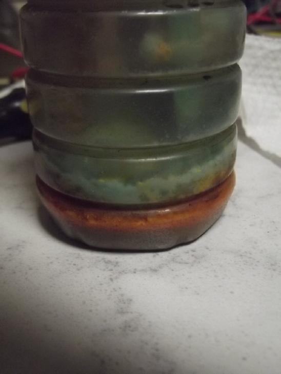 Orange sludge had piled up on the bottom of the cell with
the copper electrode. Now I notice that with the nickel one, blue-green
sludge has piled up on the bottom as it charges. Oh. Duh. These things
aren't dissolved materials, they're solid nanopowders getting through
the pores in the paper. So they're things that should be staying in the
electrodes! I thought I had that solved (at least for nickel) when I
toluened the papers? Obviously not! And the currents are poor and get
poorer because compacted powder becomes loose when a bunch of it has
left the electrode.
Orange sludge had piled up on the bottom of the cell with
the copper electrode. Now I notice that with the nickel one, blue-green
sludge has piled up on the bottom as it charges. Oh. Duh. These things
aren't dissolved materials, they're solid nanopowders getting through
the pores in the paper. So they're things that should be staying in the
electrodes! I thought I had that solved (at least for nickel) when I
toluened the papers? Obviously not! And the currents are poor and get
poorer because compacted powder becomes loose when a bunch of it has
left the electrode.
I decided to try for
another monel electrode, again using
both the parchment paper and toluened watercolor paper. I should think
that nothing should come out of an electrode and it should stay clean
on the outside. How have I glossed over so many "little details" on
this absurdly long project. But it's doing the separate perforated tube
electrodes in clear bottles of electrolyte that has finally made clear
seemingly mysterious things that have been happening. Before I could
just see the edge of the stuff coming out and thought it was just a bit
of impurity or something. For it to pile up on the bottom of the jar,
it has to be a major component of the electrode.
2nd Monel Electrode
I printed yet another tube and put a toluened watercolor
paper into it, and inside of that a piece of parchment paper. I emptied
out the old tube now only half full. A drill bit a little smaller than
the inside of the old tube "screwed" the compacted powder out. The tube
broke in half while I was doing it, which just made it easier.
I picked out the bits of paper, added some fresh monel powder to
have enough, and filled the new one. It compacted quite a lot by
pressing with a pencil, but I was still able to insert the cupro-nickel
terminal strip. at least, most of the way. Since the yellow "stuff" had
drifted out the slot in the cap, this time I covered the top with heat
glue instead of using the cap.
Hopefully this time the tubes will stay clean on the
outside and the bottle won't fill with fine stuff drifting out of the
electrodes.
Weights & measures
Tube, papers, cap: 5.20 g
CuNi terminal strip: 4.35 g
Filled weight: 34.70 g
34.70
- 5.20
- 4.35
--------
25.15 grams of monel. Less than half the mass of the monel is copper,
so call it 12 g of copper. Comparing with zinc, Cu(OH)2 would be:
(820 * 65.39/63.55) = 843 AH/Kg
Factoring in the weights of the hydroxide: 63.55 / (63.55 + 32 + 2) =
.65
843 * .65 = 549 mAH/g
549 * 12 = 6590 mAH or 6.6 amp-hours.
It's not as much as the 10 AH of the Mn side, but it's not absurdly far
off either. (3 tubes to 2 could be about right for balance? ...Assuming
both sides provide their theoretical amp-hours or both are close to the
same percentage.)
I filled a new bottle with 10% KCl electrolyte with a
small scoop of CaO, then I put the two new 'odes into it and connected
them. This time both electrodes needed charging instead of just one.
When charged it will probably be around 1.7-1.8V and should drive a
load at around 1.6. With the supply set to 1.9V, the cell started
charging at 15mA. (If Cu-Zn needed 1.6V then Cu-Mn should be about
1.9V.) Disappointing as usual, but it didn't start dropping and in an
hour it had risen to 25mA - promising!
[18th] Ups and downs. I was pleased to see it charging at 23mA in the
morning after having dropped to 15 before I went to bed. And it was
holding over 1.4V instead of 1.36, and drove a 100Ω load at over 12mA.
But when I checked it a little later all those figures were down to
those of the previous evening and the charging current was just 7mA.
I tried a short circuit for a few seconds. Current was up
from 130mA to 150-160. When I put it back on charge it sat at 40mA for
a while - even went up a bit. But 10 minutes later it was down to 8
again.
Finally I got frustrated and put the zinc 'ode back in and
put the charge back to 1.8V. It looked pretty crappy and held no
voltage to speak of. A short circuit yielded 130mA. I think shorting it
actually helped it. It started to charge a bit faster and in an hour it
held 1.3V for a while with the charge off. (Short: 190mA.) There wasn't
much "stuff" coming out -- except in a band on one side, half way down
and to the bottom. The cupro-nickel strip must have bent over to that
side and scratched/ripped the paper there as I inserted it. That might
ruin it. There was stuff at the bottom of the new bottle now. Rats! I
thought of a cunning plan: dry it off and plaster that side with heat
glue. Would it work? It might be easier just to make [yet] another
monel electrode.
I checked it just before bed. It seemed to be proceeding
well, even if very slowly with only a few milliamps of charge at 1.7
volts.
[19th] Still better. It held 1.37V when I turned off the charge, and
ran a 50Ω (22mA) load for 6 minutes dropping only 2mV from 1.124 to
1.122. Then it recharged (1.7V) for some minutes at similar current
before dropping to the familiar unit milliamps values. I decided that
if the zinc side was fully charged, it really shouldn't be part of the
equation in charging the copper oxide, and maybe the wet zinc
electrode, as it dries in the air, would oxidize (discharge) some and
be a better match in later charging. So I took it out and put the
platinum piece back in. But at 1.7V charge the current was about the
same (7mA) and I didn't want to go higher for fear of corroding the
cupro-nickel terminal at the waterline.
Much to my surprise, when I put the zinc electrode back in
the cell the voltage was .2V. It seemed to have completely discharged
as it dried, ie, all the fine zinc powder had turned in the salty wet
air into zinc oxide. Perhaps I should have expected it to. Yet the
changing current was still just a few milliamps.
It took quite an hour just to bring the voltage back up,
obviously without having imparted much charge to the zinc yet. When I
stick in a somewhat oxidized strip of zinc metal, it's much the same
low currents. If both electrodes need charging, why are the currents so
low? I am perplexed. But it was working quite well before, and the open
circuit voltage was rising much more quickly with the plus side already
having some charge. And after running a load the charging current is
way up. I guess the plus side is still quite resistant to initially
being charged, wherein its crystalline structure is probably drasticly
reformed, but once having been charged it will fairly rapidly recharge.
A few hours, mostly charging but a few times driving a 50Ω load and
shorting the cell a few times briefly, brought the zinc back up at
least to 1.3V and holding voltage a little while under load. But now
it's the zinc side that's way undercharged and the cell doesn't run
very long. I should probably make a new zinc electrode.
Zinc Electrode #2
[20th] I made a new zinc electrode, this time with the watercolor paper
inside the tube, and within that I coated parchment paper (instead of
cellophane) with the osmium dopant. Since it starts fully charged,
charging current (to charge the copper side) dropped to a trickle. And
for some reason, all the voltages were down. Like, open circuit stayed
below 1.2V, and it dropped to .7V instead of 1.1-1.2 for a 50 ohm load.
And I saw bubbles of hydrogen on the zinc tube. Maybe they were
interfering. Some discharges and rechrges brought the voltages up some.
Tube, wire, papers: 8.55 g
Total: 27.00 g
= 18.45 g of Zinc (with zircon)
[21st] It still seemed to be bubbling hydrogen. That can't be good
since it will turn the zinc into zinc hydride. I got the idea to put
the discharged zinc electrode in as well as the charged one and connect
them together. The charge in the one could charge the other and there'd
be two half-charged zincs. When I connected them the voltage dropped
from about 1.1 to .9 volts, then started rising millivolt by millivolt,
second by second. This slowed and slowed but continued until it was
almost 1.1 volts again. Why 1.1 instead of 1.3? It occurred to me that
that about .2V was the step voltage going from metallic to valence 1 to
valence 2. I had turned the charge voltage down from 1.8 to 1.7 to 1.6
volts, being afraid of deteriorating the cupro-nickel terminal strip.
Could it take 1.8V to turn the copper "cupric" rather than "cuprous"? I
turned it to 1.8V for a while. it didn't seem to help and I reduced it
to 1.6 again.
I'll hazard a guess that with the tiny charging currents,
initially some copper got charged to "cupric", especially in the
cupro-nickel strip, but that in the monel it's diluting to CuO + Cu
=> 2 Cu2O, the lower voltage form. Until the electrode is 50%
charged, the lower voltage will be the prevailing condition.
Improving Conductivity?
Thinking of that, monel, something like 64% nickel and 36%
copper, would probably be more corrosion resistant than the
cupro-nickel, which is only 30% nickel. I started looking for monel
wire for the terminal/current collector. Then I ran across fine monel
mesh, even 200 wires per inch. That could be distributed through the
electrode, eg, by winding it into a spiral that got all the powder
within, eg, .5mm of some bit of the mesh. Might that be the way to up
the currents? And the mesh itself would add capacity to the electrode.
Here I think I've hit on something major.
But an alternative might be to compress the powder more,
even to "sinter" it together by pressure. (or heat?) After all, the
surface molecules oxidize but the interior (according to my theory of
operation) stays metallic. It could be pressed either just enough to
flatten the powder spheres a bit so there's a tiny solid connection
between each particle to other particles that isn't wetted by the
electrolyte (presumably in place in the 'ode), or enough so that it
actually would become a solid object full of voids instead of a powder.
Perhaps I could do that with the hydraulic press? A 6 or 8 inch steel
pipe of just the right diameter for the electrode tube, with a solid
steel plug for each end. Put the powder in and compact it in the press,
then drive the hopefully "solid" compacted part out one end of the
pipe. (Or a shorter steel pipe and do it in sections?) Oh ya... then
how do I get the current collector into it? Hmm... 2, 3 or 4 strips
along the outside edges instead of one in the middle?
The fact that the currents seemed unchanged after doubling
up the zincs indicates that the essential current limitation is in the
monel side. But no doubt the zinc side too would benefit a lot in
current capacity from better compaction.
I couldn't find a steel ~11mm pipe to try this out. A new
idea for immediate tryout occurred to me: Find a metal pipe that fit
just over the plastic tubes, "telescoping". Then I could ram in the
electrode materials in harder (but not hydraulic press hard) without
bursting open the plastic. (The plunger or the compacting powder itself
in shifting downward, might still puncture or rip the parchment and or
watercolor paper. But worth a try.) Great, now I needed a 14mm pipe
instead of 11mm.
I found "1/2 inch" copper plumbing pipe was slightly too
small. Then I thought, wait! - there's "L", "M" and "H" copper pipe.
"M" is normal for houe plumbing, but once I had got some "Light" as
scrap. The OD was the same on all so they would fit the fittings, so
the ID had to be a bit larger with the thinner wall. Sure 'nough, I
found a piece, and it was the exact, ideal size. WOW! Now...
would it work?
Monel Electrode #3
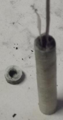 I tried it
with a new monel tube. Other than having to
sand down the plunger to fit better, it went smoothly. I would put in a
small spoon of monel powder, put in the plunger, and tap it on top with
a hammer until it just wouldn't sink down any farther. I filled the
last 3/16" with heat glue.
I tried it
with a new monel tube. Other than having to
sand down the plunger to fit better, it went smoothly. I would put in a
small spoon of monel powder, put in the plunger, and tap it on top with
a hammer until it just wouldn't sink down any farther. I filled the
last 3/16" with heat glue.
Tube, papers, two cupro-nickel current collector/terminal strips: 8.65 g
Filled with monel: 38.65 g
(NB: with heat glue, total: 39.15g)
I feared the tube wouldn't come out of the copper pipe
intact, but it slid out easily enough by pushing up on the bottom with
the plunger.
Evidently I got exactly 30.00 grams of monel into the
tube, contrasted with 25.15 grams in the previous one. Hopefully that
would make a good conductivity increase as well as store 20% more
energy.
I cleaned out a cell
bottle, refilled it with old
(filtered) 10% KCl electrolyte, added 1/4 of a tiny spoon of CaO to
keep the pH at 12-13, and stuck the new electrode and the recently made
(mostly discharged) manganese negative in. To make hydroxide to charge
the copper/monel I could have used the platinum piece and let it bubble
hydrogen, but this should work as well and be more interesting. I am
expecting something like +.1V from the copper and -1.5V from the Mn,
total 1.6V. ...if the copper charges to CuO or Cu(OH)2. For Cu2O or
CuOH it might be as low as 1.4V.
The initial voltage said about .53. I set the charge to
2.10 volts. (That's equivalent to 1.8V with zinc, given the higher
voltage of manganese.) It started drawing 40mA, which rose soon to 60+
and stayed up there for 5 minutes, then it started dropping off slowly.
Momentary voltage just off charge started at around 1.3V. In 15 minutes
it was 1.4. But these of course fell rapidly until charge was resumed.
After 20 minutes current was down to 36mA, and it wavered between
34 and 38mA for nearly an hour then went up to 39-45mA. Before I went
to bed it seemed to be headed for holding a 1.4V charge -- in just an
hour and a half on the first evening. This substantially higher current
level and faster charging doubtless indicates substantially improved
internal conductivity. Of course the bar was set awfully low to start
with and there's doubtless a long way to go yet before these cells are
running EV's or short term power grid storage. (The idea of "sintering"
or "near sintering" of the powder comes back to mind.) I'm starting to
envision potential "production" techniques rather than "one off" crude,
laborious prototype building. Whether I get there or not.
If the monel is 60% nickel and 40% copper, 30 grams means 12 grams of
copper. A piece of paper says my first zinc electrode had 14.25 grams
of zinc, and the second one had 18.45 grams. Assuming the copper moves
two electrons, one needs just slightly less copper than zinc for
balance. Assuming 18+ grams of zinc, 3 tubes of monel would about match
2 of zinc. This is much better than with nickel oxides where the
density is under 3 to zinc's 7 and AH/Kg is 300 to 820:
820/300 * 7/3 = 6.4 nickel oxides tubes for each zinc tube.
(although that gives maybe 1.7V instead of 1.1V)
For 2 tubes of zinc, 3 tubes of monel (5 total) or 13
tubes of nickel oxides (15 total).
If we compensate for the voltage difference:
1.1 / 1.7 * 15 tubes = "9.7" tubes for the nickel instead of 5 for the
monel. That's twice the bulk. It's less than twice the weight because
the nickel tubes are so much lighter. Yet nickel-zinc is noted for its
high energy density, and the monel-zinc is clearly better,
- - - - -
I must confess perplexity that the cells initially were
holding 1.3V, even 1.37, but as they charged they were eventually only
holding 1.1V. 1.1V is about what I originally expected from the
Pourbaix diagrams, but of course "losing" a seeming 18% increase in
energy and the need to connect fewer cells to attain a given voltage is
disappointing. And really they'll be rated as 1.0V or even .9V under
load. Perhaps the 1.3V+ had something to do with initially changing the
alloy structure of the cupro-nickel or monel as the metallic components
on the surface oxidized.
[22nd] After some unsatisfactory tests with monel tube #3 & Mn, I
traded monel #2 & #3 so I had what I thought was the better one in
with the two zincs. I ran a load test which seemed disappointing. It
started at only .914 volts and in 40 minutes made its way down to .796
volts. But I kept it running for two hours, and it only dropped to .791
over the rest of the time, mostly running at .795-.796. Running them
seems to be good for them. Then I left it to recharge overnight at 1.6
volts. I could hear bubbles coming out of the zinc. Since the zincs
were contributors to running the load, how could they be overcharging
and bubbling zinc while the cell recharged? Nevertheless they were
bubbling.
[23rd] Charging was down to 2mA in the AM. I tried another long test.
It was about the same as the previous except that the voltages were
about 50mV lower. Another test was down yet another 50mV. .7V seemed a
bit ridiculous. I thought of my previous flat cells, how they would get
worse but would improve substantially if I leaned a good portion of my
weight on them to make the powders more compact. I conceived that the
problem was mechanical rather than chemical.
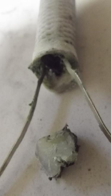 [24th] I put
the tube in the microwave oven for 9 seconds. The heat
glue wasn't softened much, but the top of the PVB tube was, and I
pulled the seal off the top to open it. I put it in the copper pipe. I
found a steel rod that fit into the top pretty well. I put it on the
press and pressed it to about 1/2 a ton. I didn't dare do more with
flimsy plastic within a pipe that was just thin copper. This was
apparently much more pressure than I had made tapping it with a hammer
as I added powder to fill it, because I had a hard time getting the
plastic tube out of the pipe. I had to put it in a vise so that the
light copper pipe was just held at two points but the plastic inside
could come out the bottom, and tap a rod into it with a hammer to get
it to budge. When I was done the top had broken off the PVB tube and it
probably got a little scrunched. It was down from 100 to 90mm tall and
the more compacted monel powder to about the 85mm mark. I used heat
glue again to seal it.
[24th] I put
the tube in the microwave oven for 9 seconds. The heat
glue wasn't softened much, but the top of the PVB tube was, and I
pulled the seal off the top to open it. I put it in the copper pipe. I
found a steel rod that fit into the top pretty well. I put it on the
press and pressed it to about 1/2 a ton. I didn't dare do more with
flimsy plastic within a pipe that was just thin copper. This was
apparently much more pressure than I had made tapping it with a hammer
as I added powder to fill it, because I had a hard time getting the
plastic tube out of the pipe. I had to put it in a vise so that the
light copper pipe was just held at two points but the plastic inside
could come out the bottom, and tap a rod into it with a hammer to get
it to budge. When I was done the top had broken off the PVB tube and it
probably got a little scrunched. It was down from 100 to 90mm tall and
the more compacted monel powder to about the 85mm mark. I used heat
glue again to seal it.
I put it back into the bottle. When I turned on the charge
it started at 118mA - it was previously below 50. That seemed to bode
well. That dropped to a little over 30, but the cell voltage stayed in
the 1.3V range instead of jumping up to the 1.6V of the power supply.
When I put on a 50Ω load the voltage stayed over 1.0 volt instead of
dropping below .7. 20 ohms was around .925V. And the voltage didn't
drop by millivolts per minute but instead
in a 50Ω load test after not much charging, output voltage rose
gradually from ~1.04 to 1.115 (+75mV!) in an hour. I had only intended
to run it for 1/2 hour as I had lots of things to do, but it was too
amazing to stop! Finally it seemed to stop rising at 1.118V. I had to
call a halt at 90 minutes, at which point it hadn't fallen even a
millivolt. Obviously it would have run for many hours - just as it
should. I couldn't resist trying a 20 ohm load... then 10... then 5
ohms... for a few minutes each. The voltage stayed above 1.1 volts for
all! In fact, running it seemed to make it stronger each time, as the
voltages rose in the few minutes each time. After some charging the
heavier loads didn't seem to work nearly as well, so there might have
been a poor connection somewhere. I turned the charge down from 1.6 to
1.5 volts. (I have the thought that with the zinc side bubbling, the
bubbles are interfering with conduction, and as they dissipate
everything improves. I have to figure out why it's bubbling and see
what it takes to eliminate the problem. It might be the soap/gel
ingredient [sodium dodecylbenzenesulfonate] bubbling rather than the
zinc itself. If so it might slow and stop by itself.)
A few hours later it was up to its old tricks. It seemed
to be holding 1.2V open circuit, but when left for a couple of hours it
was below 1.1V. When a 50Ω load was applied it dropped to .8__ volts
instead of staying over 1.___. I put it in a bottle with fresh
electrolyte but it didn't seem to help. I picked up the bottle and
banged it on the counter from an inch up and the voltage rose to ~.9__,
and with a couple more to over .95_V. Bumping the monel 'ode itself
seemed to cause changes while bumping the zincs had no effect.
But after that the charging current was up again. The cell
is doing things I don't fully understand but... I am getting the
impression that the chemistry is fine but that my plastic tubes are
inadequate to hold the monel oxides together properly. I seem to need a
new plan. Or I can try making the tubes with thicker walls? Would that
even help? Edison's perforated metal tubes for nickel hydroxide are
starting to commend themselves. It would have to be monel or
cupro-nickel walls. This again begs the question of how I might make
such a thing at home.
Charging a while seemed to have good effects. Voltages and
currents came back up. But the current at bedtime was jumping between
12 and 20mA, with different numbers flashing by on the meter with every
reading. The previous bottle had a lot of "stuff" in the bottom -
perhaps the cell was being discharged by dissolved impurities? If so
the new one should be working well by morning.
BUT I have proven the
chemistry. I don't have a super,
high current cell, but it's seems proved that the problem is in fact
insufficient compaction of the monel powder. The zinc is softer, but
could also still probably be stuffed in more firmly. Next some better
construction and better fabrication techniques need to be found. I'm
sure factories where dry cells are stuffed would have few problems.
Flat Cell
[Christmas] Reluctantly I decided to try the "flat cells in a clamp"
idea again. The one that seemed so promising but where I never seemed
to be able to make cells that didn't leak. Surely I could? The clamping
pieces could supply the pressure needed to keep the monel compacted.
First change: 6mm thick 'odes. Each cell would hold a huge amount of
energy.
Second change: Since the thin 3D printed faces took ages to print and
since electrolyte seemed to seep thought them, the faces would be
sheets of ABS. Only the cell edges would be 3D printed. Since the edges
will be pretty thick, the only places for leaks will be between the
faces and the edges. I can glue the back face on pretty solidly with
ABS cement, which seems to work better than methylene chloride. Could I
makes the faces a little larger than the frame and smear silicone all
the way around the edges? Hmm!
It still too almost an hour and a half to print the frame.
I inspected it carefully under strong light as the cement was setting
and found a couple of small gaps. I pried them open a bit more, added
glue and squeezed the offending spots.
Third change: Since it's so hard to keep the monel compacted, I'll use
sponge rubber between the front face and the edges. The harder the
clamps are pressed, the more the compaction, and even if the
copper-nickel substance "shrinks" at first with charging and
discharging (as it seemed to do), it can be compensated for by
tightening the clamps. (A big, fat square O-ring sounds ideal, if such
a things existed in the needed size.)
What do you get when you try and cram 94 grams of fine,
fluffy zinc flakes into a flat 56cc box bottom? A mess! I despair. OTOH
if you can do it, that's 94g * 820mAH/g = 77 amp-hours of zinc in a
tiny little box. Maybe I can compact it into a sort of a solid blob or
briquette and set it in place?
I decided the mess just wouldn't do. I found the 50x50mm
compactor I made some years ago, filled it with zinc, and pressed it to
about 2-1/2 tons. I made four very brittle briquettes to fill the
bottom electrode area of the flat cell, about 30 grams each. Two fit
whole and the others had to be sliced, with a corner of one being
discarded. (It would be simpler if I made the cell multiples of 50mm.)
They came out only 3-4mm thick so even with the copper foil they didn't
quite fill to the 6mm electrode separator mark. I weighed it as 112.7
grams. Subtract about 1 gram for the zircon is 111.7. At zinc = 830
mAH/g that's 91.6 theoretical amp-hours.
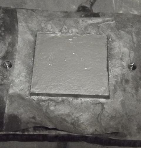 Compacted square of zinc
Zinc electrode: Almost four
50x50mm briquettes,
two sliced up to fit.
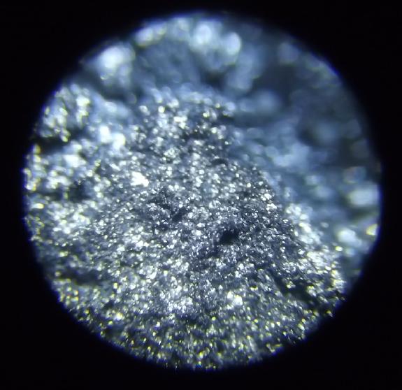
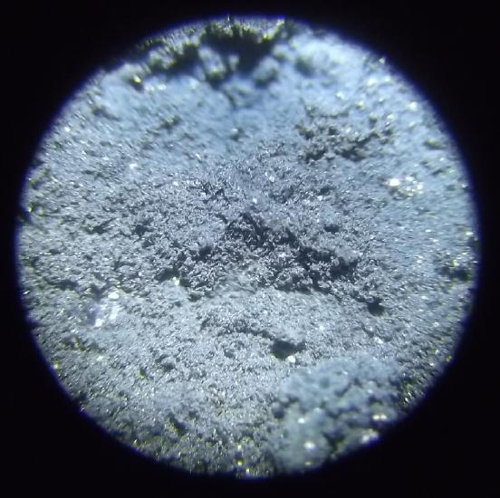
"Zinc powder flakes" or "zinc powder"? I decided the powder was so fine
electrolyte might have trouble penetrating it and used the flakes.
(I didn't use any recycled dry cell zinc powder in this one.)
If the monel matches the zinc it will be by virtue of
being more dense - more the mass in a similar volume. Given the
fluff of the zinc flakes and the density of the monel powder, it might
well do it. A cell of that small size with almost 100 amp-hours of
charge would be impressive, given that a lot of the volume is plastic
and a water reservoir. (And even tho it's only at 1.1 volt.)
[26th] I cut & doped a piece of parchment paper with the osmium
dopant. Then I soaked some watercolor papers with toluene and let them
dry, twice. I put those on top of the zinc in the flat cell and poured
in some of the SDBS solution and let it soak for a while. There seemed
to be much less when I poured it back - presumably the zinc and papers
had soak up quite a bit.
It was time to do the monel electrode. I had cleaned most
of the equipment and washed of the bench, but the compactor was still
covered with zinc. I decided to do four extra zinc squares for the next
cell. Zinc powder spreads all over everything. In case I wasn't already
quite sick of the "tin woodsman" look, repeatedly washing my hands and
cleaning up, by 2-1/2 hours later I most certainly was.
I tried
compacting monel. Some of it made a brittle
brittle 'briquette', but much of the square remained as loose powder.
Now what? Also it didn't compact as much as the zinc. Filling the space
with powder made a square 40 grams and (where it held together) 6.5 mm
thick. 35 grams of monel with only 1/3 being copper would be only 1/3
the theoretical amp-hours of the zinc (also over 30 grams per piece),
or around 30 amp-hours, even with copper moving two electrons per
reaction. This suggests making the zinc side thinner, the monel a full
6mm, and lowering the dividing ledge in the plastic edge to compensate.
I was trying to take some
videos as I assembled the new
cell as well as a picture or two. The camera ran out of memory. The
rest of the evening turned into a search through two dozen USB drives
looking for the one I was putting videos on, since the main drive of my
computer wasn't up to accumulating hundreds of gigabytes of them. By
the time I found it, copied a zillion video files and erased them off
my camera, it was late. (I really must get around to uploading a few
"Exploring Battery Making" videos to youtube! The first one is a year
old!)
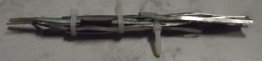
It also began shedding coppery particles to settle at the
bottom of the bottle. 70:30 cupronickel probably has too much copper
compared to the amount of nickel: the copper isn't being held in place.
Hopefully it will just shed copper until they are in balance?
I started asking myself "Why would I go to the trouble of
using monel powder when solid sheet metal is so simple and seems to
work so well?" All I needed to do was arrange pieces appropriately and
have papers to keep the shedded copper from roaming. There is the
question of how well cupro-nickel will hold together compared to monel,
but monel sheet metal is available (if very costly) in case the former
doesn't last. And of what thickness of sheet metal will hold together
but maximize reactive surface. I'll try the 70:30 first as it's by far
the most common copper-nickel alloy. I see 60:40 (doubtless better) but
not for retail sale.
So, back to the clamped flat cell, instead of compacted monel
powder with one CuNi current collector and terminal sheet, I put 5
sheets of CuNi in with little CuNi strips to separate them. They
weighed about 255 grams. They fit pretty perfectly as to thickness. I
cut a rubber sheet to fit over the entire face, put the ABS sheet on
that, and clamped the cell closed. I spent the better part of an hour
adding a bit of water and a bit of water (without measuring) until a
little stayed up in the top reservoir.
In a couple of hours I was seeing initial charging
currents over 400mA steadying out over 200, and it would drive a 5 ohm
load at over a volt for 30 seconds, then 3 minutes and later, 10
minutes. Short circuit current was about an amp. And for some strange
reason, no water was leaking out the bottom! Could I really have made a
non-leaking cell? In the evening I ran a 10 ohm load for all but an
hour before it dropped below 1.000 volts. And it still has a very long
way to go before it's fully charged. Soap bubbles were coming out the
filler hole. It recovered to 1.175V in ten minutes before I turned the
charge back on - ~300mA, dropping soon to under 150. The soap bubbles
receded when it was on charge.
[28th] Further charges and discharges appeared to show slowly
deteriorating performance. I'm not at all convinced this has intrinsic
chemical
reasons.
[29th] I figured the shedding of sludge in the bottle is due to the
thought that 70:30 is doubtless too much copper for the amount of
nickel, and that there was probably sludge buildup in the flat cell
too. (If I had sheet metal with more proportion of nickel I'd have used
it.)
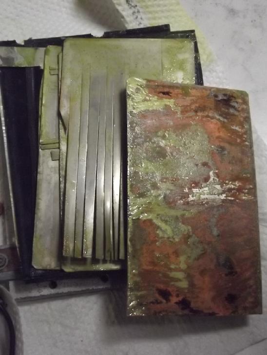 Not gluing the
cell shut was a good idea. I opened it.
Four of the five CuNi sheets seemed almost untouched. Only the very
edges of some had any change. Essentially only the inside side of the
fifth sheet, the side against the separator papers, was being used. It
had attained a coppery color over most of that surface. Sludge on top
could be wiped off. Probably the sludge insulated the metal and
accounted for the deteriorating performance, and the fact that most of
the sheets weren't reacting must account at least partly for the low
amp-hours. Some patches where there was still nickel color showing were
probably from uncleanness - finger grease or something preventing the
electrolyte from reaching the metal. I can and will of course clean it
up. It's possible that CuNi 60:40 (or monel - eg, 35:65) will charge
without making sludge. If not, I assume they will only do it initially.
(That is something I believe, but will have to definitely prove by
longer operation.) Perhaps I need to pre-charge the sheets to the
coppery color and clean the sludge off them before using them again in
the cell.
Not gluing the
cell shut was a good idea. I opened it.
Four of the five CuNi sheets seemed almost untouched. Only the very
edges of some had any change. Essentially only the inside side of the
fifth sheet, the side against the separator papers, was being used. It
had attained a coppery color over most of that surface. Sludge on top
could be wiped off. Probably the sludge insulated the metal and
accounted for the deteriorating performance, and the fact that most of
the sheets weren't reacting must account at least partly for the low
amp-hours. Some patches where there was still nickel color showing were
probably from uncleanness - finger grease or something preventing the
electrolyte from reaching the metal. I can and will of course clean it
up. It's possible that CuNi 60:40 (or monel - eg, 35:65) will charge
without making sludge. If not, I assume they will only do it initially.
(That is something I believe, but will have to definitely prove by
longer operation.) Perhaps I need to pre-charge the sheets to the
coppery color and clean the sludge off them before using them again in
the cell.
The metal sheets extended to the edges and while the
electrolyte could get through and fill the spaces, I wasn't sure they
had been filled judging by the amount of liquid that came out when I
opened it, and it evidently wasn't much of an ionic connection. The
second sheet with the many cuts to make gaps was probably the way to
go, but of course almost nothing was getting through even to that
sheet.
Essentially it was operating with 1/10th of the CuNi faces in use.
Ideally all the sheets might be perforated in a zillion places, or
might be a mesh instead of sheets, or mesh and powder might work
better.
The sheets was just easiest for this experiment.
Given that it could source almost two amps when shorted,
if all ten surfaces were contributing it might perform rather well.
[31st] After a couple of days of
charging voltages and performance were
dropping again so I opened the cell again. The sheet against the
separator was again the only really coppery colored one, altho there
were a few other spots on the other sheets. I brushed them off with a
fingernail brush. The green came off easily. The black needed
scotchbrite.
Copper (II) oxide is black. Copper (II) hydroxide is green. Copper (I)
oxide is red. Copper (I) hydroxide is unstable and is said to hardly
exist. I came to some quite tentative conclusions:
- The new sheets (with zinc negatives) need at least 1.6 volts to
"crack" the shiny silver surface into reacting. 1.8V is faster. 2 volts
or more will start corroding them away entirely.
- The coppery colored surfaces are copper held in place by the
cupro-nickel under the surface. I believe this is the appearance of the
"finished" material once the electrode is initially charged.
- In spite of nickel hydroxide and oxyhydroxide also being turquoise
and black, the colors I was looking at were mainly copper and copper
oxides.
- There was no apparent copper (I) oxide [deep red] or hydroxide
[unknown]. Except for the silvery untouched parts, it was either orange
copper metal or copper (II) hydroxide, and possibly some black copper
(II) oxide.
- The green was copper hydroxide. It seems to 'stick' together but
doesn't adhere well to the metal sheet. It can be scraped or brushed
off easily. I suspect it forms because there's too much copper for the
percentage of nickel in the alloy. It seems poorly-conductive itself
(megohms) and
when it coats the sheets they don't seem to conduct electrolyte any
more,
causing the performance to deteriorate.
- The black just might have been copper oxide. Contrary to the
hydroxide, it was strongly adhered to the metal. But it was kind of
shiny and in distinct rather smallish patches. More like some kind of
oxidized finger grease or other contaminant? IF it's copper oxide it's
probably held in place by the nickel elements behind it. Then it would
be the desired "charged" state of the sheet and I did wrong to scrub it
off. But I think the coppery color is what is wanted, which I suspect
is probably "nickel cuprates" like Ni(Cu2O3) or Ni(Cu(OH)3)2 sorts of
compounds in varying oxidation states.
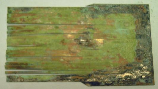 Coppery, green and black areas.
(The black could be oxidized SDBS? or copper oxide?)
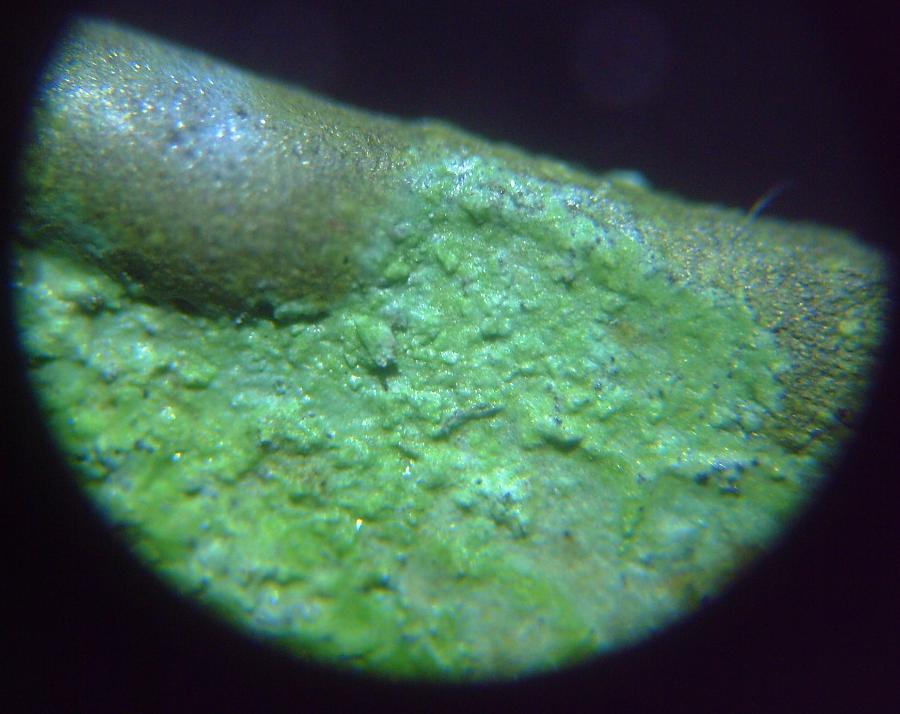 Green areas under microscope
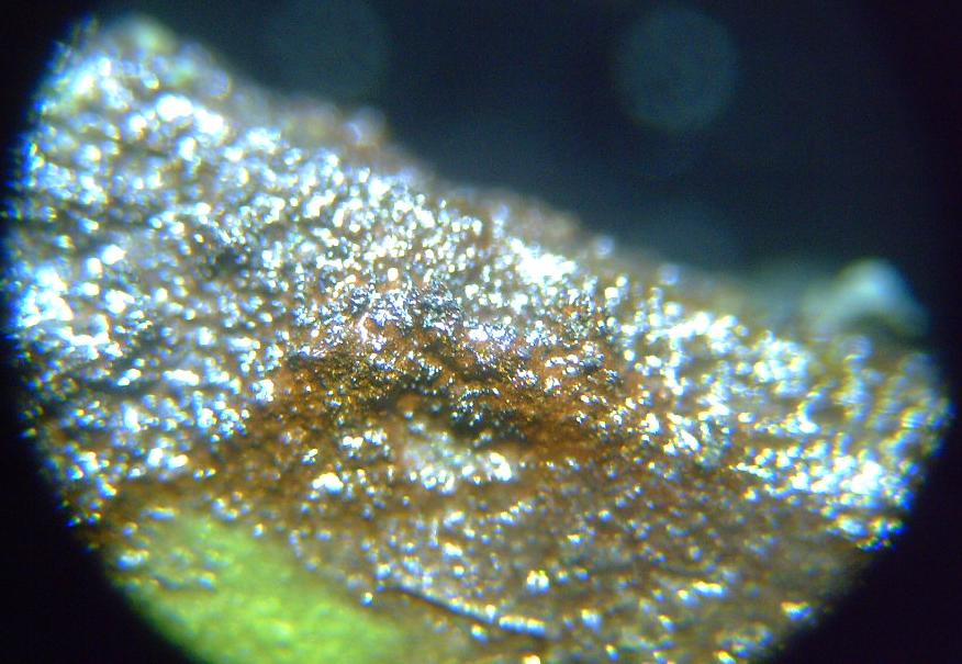 Microscope view of the three main
colors: still
silvery, orange and green.
Microscope view of the three main
colors: still
silvery, orange and green.
When I put the cell back together it didn't just leak. The
electrolyte poured out the bottom as I poured it in at the top. I
couldn't seem to see where it was leaking and I tried sealing it about
three times with the same result. The rubber face had at least one cut
in it. I think I need sheets of sponge rubber that would seal with much
less pressure. (I ordered some on AliExpress, not expecting to find
them locally.) Finally I just laid it in a vat and filled it with
solution, dumped in a small spoon of calcium oxide, and propped up the
back so the terminals were out of the water.
That night I switched it from charge to 10 ohms load. The
voltage dropped at once to .88 V and soon rose to .896 V. I was again
disappointed by the voltage being lower than previously. But the CuNi
seems to drop in voltage as the cell "formed up". I decided this time
to let it run a while. It sat at .896 V (& 89 mA) for almost 15
minutes. By 25 minutes it was down to .893 V. Three millivolts drop in
25 minutes? I never get such a small drop. I think I'm expecting the
voltage to be too high, then when it drops below 1.0 volts I'm
disappointed and I stop the test. If it has anything like the amp-hours
it theoreticly should, perhaps it puts them out below one volt. After
30 minutes it was down to .885 V. If I then switched to a lighter load
of course the voltage was higher - .98 V for 20 Ω (49 mA), 1.04 V for
35 Ω and 1.06 V at 50 Ω (20 mA). Off load it rose above 1.1 V again.
Nickel-metal hydride cells discharge from about 1.35 volts to 1.15 and
then fall off a cliff, dropping rapidly to nothing. So far, with a 50
ohm load it seems one can run copper oxide for many hours down to about
.75 volts before it peters out. But this is probably dependent on
construction and internal resistance, and the end may be at a higher
level (.85-.95 V?) in a well made cell.
A Design for a Manufactured CuNi-Zn Battery?
In the first days of January I ran some tests and found
that lower voltages that were disappointing me were owed to poor
connections between the CuNi sheets inside the cell. (The inner sheet
did most of the chemistry, but the terminal tab was on the outer sheet,
and the surfaces between naturally oxidized.) The chemistry was working
fine. Tightening the clamp screws brought the voltages back up. I
expect I should call it a "1.0 V" battery when under load. The
initially (and unexpectedly) higher "1.3 V" levels were evidently
unsustainable in recharging.
I came up with a plan now for how to make cells with high energy and
currents
that should continue working well. Without doing a detailed forecast, a
heavy box something like 3 by 6 inches by 3 inches tall (not counting
terminals) should hold hundreds of actual amp-hours. The plan isn't the
most sophisticated or the most economical at large scale, but it should
work at small scales and for early production. If the top is screwed on
it would be highly amenable to maintenance or modification should those
be needed or desired. A short can be repaired or a bad electrode
replaced.
The monel/CuNi electrodes would be quite like Edison's
plates: perforated sheets of about 28 gauge CuNi formed into 6mm thick
rectangular "pockets" packed with fine monel/CuNi/Cu powder (whatever
works best - to be determined) mixed with graphite powder for better
conductivity, and then crimped or welded shut on all sides and riveted
(CuNi or plastic) at middle points so they can't bulge. Connection tabs
will be integral to one of the perforated sheets or welded to it. This
is better than Edison's in that the CuNi sheets themselves are also
active material, not just extra weight.
Designs for the zinc are more flexible. There is less
tendency to swell and lose connectivity. I'm thinking similar pockets
maybe 5mm thick (inside) of perforated plastic (3D printed?), with a
perforated sheet of copper foil in the middle, again having a terminal
of copper extended from or welded to it. The doped parchment paper
would go inside around the edges with the whole soaked in SDBS for an
hour.
These individual electrodes would be packed alternately
into trays with toluene treated papers between to isolate them, the
trays sized to hold not much excess water and lids screwed (or glued)
onto them, with a screw-on cap for filling and a tiny air hole to
release pressure.
This would be "manufacturing" and there are hurdles to it
at any scale - even "prototyping" scale. The CuNi sheets are hard and
not at all easy to perforate. The pin frogs I was using for thin foil,
graphite gasket or plastic are totally inadequate. Nails are hardly
hard enough. Any anyway tiny, closely spaced holes are best. Then there
has to be some piece of equipment to press the perforated sheets
together and crimp (or weld) and rivet them with the CuNi powder being
compacted inside. Molded case parts will be required. (One thing I can
and should buy ready-made is a good "industrial" tack welder for copper
& CuNi/monel.)
Summary
So far it's not huge. Currents are in tens of milliamps
instead
of hundreds. But it hasn't deteriorated or a terminal corroded off in
the first days or weeks. Copper seems to work great as a current
conductor on the zinc side,
and on the plus monel should be a better terminal than 70:30
cupro-nickel if that does eventually corrode (no sign yet). A graphite
rod is certain if nothing else works long
term. The cells should last ages in principal.
After all but 16 years, I seem to have a real, valuable battery
chemistry. In
principal. What remains seems to be "perfecting" it to make practical,
working cells in at least moderate quantities.
Electricity
Generation
My Solar Power System
The Usual Daily/Monthly/Yearly Log of Solar
Power Generated [and grid power consumed]
(All times are in PST: clock 48 minutes ahead of local sun
time, not
PDT which
is an hour and 48 minutes ahead. (DC) battery system power output
readings are reset to zero
daily (often just for LED lights, occasionally used with other loads:
Chevy Sprint electric car, inverters in power outages or other 36V
loads), while the
grid tied readings are cumulative.)
Daily Figures
Notes: House Main
meter (6 digits) accumulates. DC meter now
accumulates until [before] it loses precision (9.999 WH => 0010
KWH), then is
reset. House East and Cabin meters (4
digits) are reset to 0 when they get near 99.99 (which goes to "100.0")
- owing to loss of second decimal precision.
Km = Nissan Leaf electric car drove distance, then car was charged.
New Order of Daily Solar Readings (Beginning May 2022):
Date House, House, House, Cabin => Total KWH Solar [Notable
power
Uses (EV); Grid power meter@time] Sky/weather
Main
DC East
November
30th 855.75, 3.03, 33.99, 20.26 => 2.50 [11117@17:00]
December
1st 856.18, 3.08, 34.19, 20.29 => .71 [11144@17:00]
2d 858.62, 3.12, 35.07, 20.36 => 3.43 [11182@24:30]
3rd Oops ?, ?, 35.66, 20.41 => 1.93
(est) [?]
4th 859.87, 3.38, 35.68, 20.43 => .37 [11216@17:00]
Storm overnight, morning.... Power failure most of day. (freezer: DC)
5th 860.65, 3.62, 36.14, 20.50 => 1.55 [11235@17:00]
6th 863.21, 3.74, 37.44, 21.31 => 4.74 [11268@16:30] Sun but cold -
frost 'till noon.
7th 863.24, 3.78, 37.49, 21.33 => .13
[11293@17:00]
8th 864.33, 3.86, 38.26, 21.95 => 2.56 [11319@17:00]
9th 865.80, 3.94, 39.18, 22.54 => 3.06 [55Km; 11356@21:00;
55Km]
10th 868.51, 3.98, 40.56, 23.75 => 5.34 [11380@17:00]
11th 869.35, 4.02, 41.09, 24.24 => 1.90 [11403@17:00]
12th 869.45, 4.09, 41.17, 24.34 => .35 [11428@17:00]
13rd 871.10, 4.20, 42.19, 25.14 => 3.58 [55Km; 11454@17:00]
14th 871.85, 4.32, 42.69, 25.55 => 1.78 [11477@17:00]
15th 872.12, 4.37, 42.82, 25.70 => .60 [11501@16:30]
16th Oops =============> 1.20 est [105Km]
17th 873.36, 4.46, 43.40, 26.19 => 1.20 (2.40 apportioned) [55Km;
11568@17:00]
18th 873.40, 4.49, 43.44, 26.22 => .14 [11601@17:00]
19th 874.24, 4.57, 43.88, 26.70 => 1.84 [55Km; 11621@17:00]
20th 875.08, 4.61, 44.25, 27.09 => 1.86 [11649@17:00]
21st 875.13, 4.65, 44.29, 27.12 => .16 [11671@17:00] Drizzle
all day
22d 877.08, 4.71, 45.20, 27.65 => 3.45 [11689@17:00] Look! A
strange big bright thing in the sky!
23rd 877.90, 4.76, 46.59, 27.99 => 1.60 [85Km; 11727@22:00; 55Km]
24th 879.31, 4.83, 46.60, 28.59 => 3.09 [11756@17:00; 10Km]
Sunshine, then a dark and stormy night...
25th 879.75, 4.87, 46.67, 28.63 => .59 [11778@19:00] Power
fail way before dawn, 3(?) hours (night of 24th-25th).
26th 881.57, 5.16, 48.07, 29.62 => 4.50 [11807@17:00]
27th 881.64, 5.21, 48.14, 29.70 => .27 [11827@17:00]
28th 883.26, 5.31, 48.99, 30.38 => 3.35 [50Km; 11855@16:30]
29th 883.28, 5.33, 49.01, 30.40 => .08 [85Km;
11887@16:30]
30th 884.26, 5.42, 49.42, 30.96 => 2.04 [55Km; 11929@22:00; 50Km]
31st 884.71, 5.46, 49.57, 31.22 = > .92 [11959@17:00]
January 2024
01st 885.06, 5.51, 49.70, 31.38 => .69 [11980@17:00]
02d 885.18, 5.59, 49.78, 31.50 => .40 [12007@17:00]
03rd 885.49, 5.65, 49.88, 31.69 => .66 [12032@17:00;
55Km]
04th 887.45, 5.73, 51.18, 32.49 => 4.14 [55Km; 12063@17:00]
05th 887.83, 5.84, 51.35, 32.75 => .92 [90Km;
12097@16:30]
06th 890.62, 6.01, 52.81, 34.25 => 5.85 [60Km; 12137@22:00; 50Km]
Sunshine!
07th 891.02, 6.13, 53.02, 34.52 => 1.00 [12164@17:00]
08th 891.17, 6.17, 53.09, 34.62 => .36 [12191@16:30]
Chart of daily KWH from solar panels.
(Compare December 2023
(left) with November 2023 & with December 2022.)
Days of
__ KWH
|
December
2023
(18 C's)
|
November 2023
(18 then 14 C's)
|
December 2022
(18 collectors)
|
0.xx
|
11
|
5
|
9
|
1.xx
|
9
|
3
|
3
|
2.xx
|
2
|
11
|
5
|
3.xx
|
6
|
4
|
6
|
4.xx
|
2
|
3
|
5
|
5.xx
|
1
|
1
|
3
|
6.xx
|
|
1
|
|
7.xx
|
|
2
|
|
8.xx
|
|
|
|
Total KWH
for month
|
57.93
|
89.06
|
79.97
|
Km Driven
on Electricity
|
771.8
(110KWH?)
|
811.0 Km
(120KWH?) |
793.1 Km
(120 KWH)? |
Things Noted - December 2023
* The DC system in the cabin is no longer using much as the battery is
charged. However it is not performing well as the delivered voltage
rises to 60+volts and the balance charger disconnects the battery from
the renegade solar charge controller. So I turned it off: the solar
panels will connect to the DC only when it specificly needs charging.
I'm about ready to toss the solar charger in the garbage.
* This December must have been even cloudier than December 2022.
Monthly Summaries: Solar Generated KWH [& Power used from
grid KWH]
As these tables are getting long, I'm not repeating the log of monthly
reports. The reports for the first four full years (March 2019 to
February 2023) may be found in TE
News
#177,
February
2023.
2023 - (House roof, lawn + DC + Cabin + Carport, Pole) Solar
Jan KWH: 40.57 + 3.06 + 28.31 + 21.85 = 93.79 Solar [grid: 1163; car
(very rough estimates): 130]
Feb KWH: 59.19 + 2.70 + 38.10 + 32.47 = 132.46 Solar [grid: 1079; car:
110]
(Four years of solar!)
Mar KWH: 149.49 + 2.72 + 53.85 + 92.08 = 298.14 Solar
[grid: 981; car:
140]
Apr KWH: 176.57 + 2.71 + 121.21 + 108.34 = 408.83 [grid: 676; car: 160]
"Lawn" collectors moved to South
"Wall"
May KWH:266.04 + 2.04 + 194.13 + 180.31 = 642.52 [grid: 500; car: 175]
Jun KWH: 237.55 + 3.70 + 172.56 + 126.31 = 540.12 [grid: 464; car: 190]
July KWH:236.99 + 1.95 + 169.16 + 155.21 = 563.31 [grid: 343; car: 180]
Aug KWH:223.61 + 1.78 + 158.31 + 134.40 = 518.00 [grid: 305; car: 130]
Sep KWH:124.33 + 2.33 + 92.76 + 76.23 = 295.65 [grid:
501; car: 150]
Oct KWH: 94.26 + 2.70 + 55.01 + 56.11 =
208.08 [grid: 842; car: 170]
Nov KWH: 45.70 + 3.10 + 24.35 + 15.91
= 89.06 [grid: 760; car: 120]
Dec KWH: 28.96 + 2.43 + 15.58 + 10.96
= 57.93 [grid: 815; car: 110]
Annual Totals
1. March 2019-Feb. 2020: 2196.15 KWH Solar [used 7927 KWH
from grid]
2. March 2020-Feb. 2021: 2069.82 KWH Solar [used 11294 KWH from grid]
(More electric heat - BR, Trailer & Perry's RV)
3. March 2021-Feb. 2022: 2063.05 KWH Solar [used 10977 KWH from grid]
4a. March 2022-August 2022: in (the best) 6 months, about 2725 KWH
solar - more than in any previous entire year!
4. March2022-Feb. 2023: 3793.37 KWH Solar [used 12038 KWH from grid]
Money Saved or Earned - @ 12¢ [All BC residential elec.
rate] ; @
50¢ [2018 cost of diesel fuel to BC Hydro] ; @ 1$ per KWH [actual
total
cost to BC Hydro
in 2022 according to an employee]:
1. 263.42$ ; 1097.58$ ; 2196.15$
2. 248.38$ ; 1034.91$ ; 2069.82$
3. 247.57$ ; 1031.53$ ; 2063.05$
4. 455.20$ ; 1896.69$ ; 3793.37$
It can be seen that the benefit to the society as a whole
on Haida Gwaii from solar power installations is much greater than the
cost savings to the individual user of electricity, thanks to the heavy
subsidization of our power
owing to the BC government policy of having the same power rate across
the entire province regardless of the cost of production. And it can be
insurance: With some
extra equipment and a battery, sufficient solar can deliver essential
power in
electrical outages however long. (Feb 28th 2023: And it's probably well
over 1$/KWH by now the way inflation of diesel fuel and other costs is
running.)
http://www.TurquoiseEnergy.com
Haida Gwaii, BC Canada