Turquoise Energy News Report #172
Covering
September
2022 (Posted October 9th 2022)
Lawnhill BC Canada - by Craig Carmichael
www.TurquoiseEnergy.com
= www.ElectricCaik.com
= www.ElectricHubcap.com
Feature: Successful Tests:
Magnetic Variable Torque Converter with Planetary Gearset Moves
Miles ZX40 Truck (see in Month in Brief, Electric
Transport;
also see Video of
test prototype working. This design works really well -- will change
the automotive industry!)
Month In "Brief"
(Project Summaries etc.)
- Cabin - Halbach "Array" Magnet Rotor Configurations - Great Variable
Torque Converter at Last! - Power Outage Preparedness
In
Passing
(Miscellaneous topics, editorial comments & opinionated rants)
- Proactive Approach to Democracy - Asteroid Dimorphos: Ahrrrg,
Monochrome
Again!!! - How Famines Develop Rapidly - Satellites or Armed Drones? -
Smol
Thots (Planetary Carrying Capacity Chart, more...) - ESD
- Detailed
Project Reports
-
Electric
Transport - Electric Hubcap Motor Systems
* Variable Torque Converter with Planetary Gear: a Magnetic Method -
Assembling the unit - Installing batteries and getting the truck
running again - Halbach Magnet Rotor Configuration: Double the
magnetism (for axial flux BLDC Motors, too!) - Installation -
Tests: Problem; then SUCCESSFUL OPERATION - Video on Youtube -
Improved with Halbach magnet rotor.
* Sprint Car: Tires, TK15 Coulometer to track state of charge,
volts, amps
* Thoughts: Unipolar Electric Hubcap Motor With Halbach Magnet
Configuration
Other "Green"
& Electric Equipment Projects
* Gardening: Some Fall Harvesting - Salal berry Rake
Electricity Storage:
Batteries [no
reports]
Electricity Generation
* My Solar Power System:
- The Usual Latest Daily/Monthly
Solar Production log et cetera - Monthly/Annual Summaries,
Estimates, Notes
Solar power generation for the month was 406.02
KWH. That's well over double most previous Septembers, with the sunny
weather and 18 solar panels instead of 12. (If - when - I move the 3
panels from the lawn up onto a 45° frame on the carport roof
(sunniest place), the figures should improve still further!)
On my 'cabin' I almost finished another 1/2 of one
of the outside walls. (In the meantime someone up the road has put up a
whole larger house this summer, and it's ready for the siding, windows
and doors. Mine is taking 'forever'.) Further work awaits Perry
removing his RV... very soon. Hopefully the weather won't be too
miserable to continue with the next section. Then in the spring I'll
pull out the travel trailer too, and finish the last wall. Then there's
the floor, walls & ceiling and the whole interior...
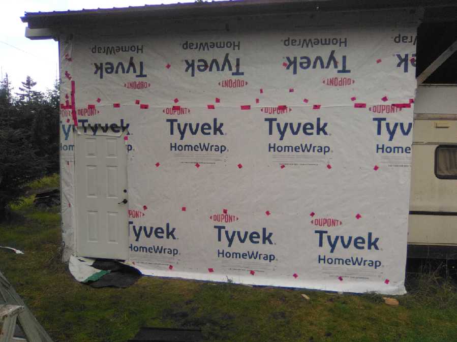 Half a wall with concrete footing, framed,
sheeted and wrapped
Half a wall with concrete footing, framed,
sheeted and wrapped
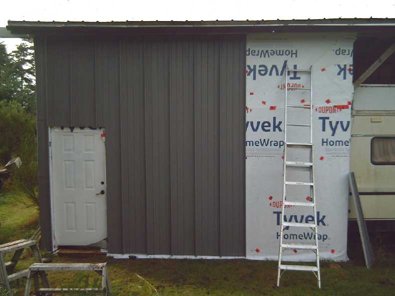 Some siding done by the end of
the month.
Some siding done by the end of
the month.
(There's no more loose siding: the rest is covering lumber piles!)
The 5 full pieces here had been covering my utility trailer in the
bushes. The spruce needles left
black dots of pitch all over them and they took much longer to clean
with Comet than to install.
I'm going to have almost no 120VAC wiring inside, and what
there is will be shielded. Just a plug or two on the east wall. Instead
for lights and plugs I'll use a 36VDC system with the solar panels and
batteries, and a plug-in adapter to maintain charge when there's no sun
or if I'm using too much power. If indeed AC power fields are what's
keeping my tinnitus going (and if so, doubtless that of many,
many other people), it'll also have grounded alume (AKA aluminum,
aluminium) walls and steel
roofing to shield it from the field of the high voltage power line by
the highway only too close by. (If a cell phone won't work inside
except by a window, I'll
know it's good!) I'll sleep in the cabin, but I suppose I'll still have
to do cooking and most things in the house. So it might not eliminate
the tinnitus, and maybe not even reduce it definitively. If it doesn't
I can make a point of spending some whole days in it to see if that
works. It's worth trying to find out. It's almost impossible to spend
days away from AC electric fields unless one goes camping in the
woods or something - even most campgrounds have power lines these days.
Halbach Magnet Rotor Configurations
 [12th] I ran
across the Halbach concept, again, this time in a youtube video, where
it was
shown for a homemade axial flux BLDC motor in a way that finally got my
brain in gear. In everything I've seen before all the magnets in the
"array" were clumped together inline in a row. Somehow the term "array"
confused me, I didn't understand the concept and I lost interest. In
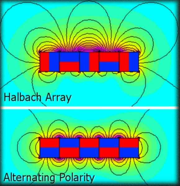
this video a flux diagram was shown with the usual sort of 5 magnet
cluster, but this one shows the idea clearly. (If the top figure is a
Halbach "Array", why is the bottom one not an Alternating "Array"?)
[12th] I ran
across the Halbach concept, again, this time in a youtube video, where
it was
shown for a homemade axial flux BLDC motor in a way that finally got my
brain in gear. In everything I've seen before all the magnets in the
"array" were clumped together inline in a row. Somehow the term "array"
confused me, I didn't understand the concept and I lost interest. In
this video a flux diagram was shown with the usual sort of 5 magnet
cluster, but this one shows the idea clearly. (If the top figure is a
Halbach "Array", why is the bottom one not an Alternating "Array"?)
 On his actual
axial flux rotor the magnets only touched (if at all) at the inner
corners. Wait! A Halbach "array" will still work, with gaps between the
magnets? on a rotor? This was never mentioned. Then I could actually
use it in my own axial flux rotors - Awesome!
On his actual
axial flux rotor the magnets only touched (if at all) at the inner
corners. Wait! A Halbach "array" will still work, with gaps between the
magnets? on a rotor? This was never mentioned. Then I could actually
use it in my own axial flux rotors - Awesome!
Basicly by adding "sideways" magnets between norths and
souths, most of the flux
comes out one ("front") face, while very little comes out the opposite
("rear") face. This might virtually double the strength of the
permanent magnet rotor's field facing the stator, and hence increase
the torque per amp of motor current.
In addition, with little flux through the rear, a steel
rotor to carry that flux between magnets is evidently not needed. A
steel magnet
rotor need only be thick enough for mechanical strength, not magnetic
flux capacity, so the motor can be a little lighter.
 In another
application, such a rotor should also obviate the need for the Piggott
type type axial flux alternator with a magnet rotor on each side of a
thin iron-free stator. One rotor with a greater field should be
sufficient, which would simplify the one shown here (from TE News #124). Or, two rotors
could match a stator an inch thick and more instead of 1/2 inch. That
would hold a lot of copper windings! Or such a higher powered unit
could more simply be two rotors and two 1/2 inch stators. (Or one rotor
with Halbach configured magnets on both sides between two stators.)
Thinner
stators should make for better cooling of the coils.
In another
application, such a rotor should also obviate the need for the Piggott
type type axial flux alternator with a magnet rotor on each side of a
thin iron-free stator. One rotor with a greater field should be
sufficient, which would simplify the one shown here (from TE News #124). Or, two rotors
could match a stator an inch thick and more instead of 1/2 inch. That
would hold a lot of copper windings! Or such a higher powered unit
could more simply be two rotors and two 1/2 inch stators. (Or one rotor
with Halbach configured magnets on both sides between two stators.)
Thinner
stators should make for better cooling of the coils.
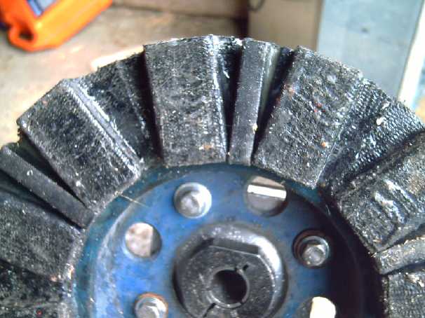 And a Halbach
configured rotor in the torque converter I was making would have much
more flux too. After initial tests of my new torque converter I added
six thin magnets (3/8" x 1/2" x 2") on their sides to my existing
rotor between other magnets. It definitely increased the flux - see
next.
And a Halbach
configured rotor in the torque converter I was making would have much
more flux too. After initial tests of my new torque converter I added
six thin magnets (3/8" x 1/2" x 2") on their sides to my existing
rotor between other magnets. It definitely increased the flux - see
next.
Great Variable Torque Converter at Last: prototype made and tested!
Well, this is a major "ultra efficient EV" component I've
been trying to create since June 2009, with various half-baked ideas
and various results but none really satisfactory. Finally last month I
conceived the best pieces, put together in the right configuration to
make it all work: a planetary gearset, with magnetic coupling between
two
of
its
elements. I described it in theory in last month's
issue, and built one for the Miles ZX40 EV truck this month. Some short
"jury rigged" tests proved it works well, smooth and effective, and
making the magnet rotor "Halbach" tweaked the magnetic-mechanical
proportions into what appears to be a good balance. Charts (see
detailed report under Electric Transport) show the theoretical
efficiencies, even under various magnetic coupling strength scenarios,
to be well over 90% when crusing at typical vehicle speeds, which is
better then the 80+ percent of today's "improved" automatic
transmissions.
Operation
Consider at low vehicle speed the motor turning at 50 RPM
and the
planetary gear body virtually stationary, balanced between moving the
truck wanting to push it backward and the magnetic drag pulling it
forward.
The gear reduction ratio is then the 5 to 1 of the planetary gear.
Now consider driving at 50 KmPH using the same torque. The
drive shaft is then turning about 1100 RPM (for the test truck). The
difference of turning
between the motor and the planetary gear body for the same torque is
still 50 RPM. But they
are both spinning. For 1100 RPM output, the motor is turning at 1140
RPM and the body
1090 RPM in the same direction.
So the gear effective ratio is 1140/1100 or 1.036 to 1.
At higher motor torque for acceleration, the RPM of the
slip increases, making higher effective gear ratios at the same speeds
for more torque and power to the wheels. The higher the vehicle speed,
and the lower the power required, the lower the percentage losses and
the nearer the gear reduction approaches 1 to 1 with everything
spinning in unison.
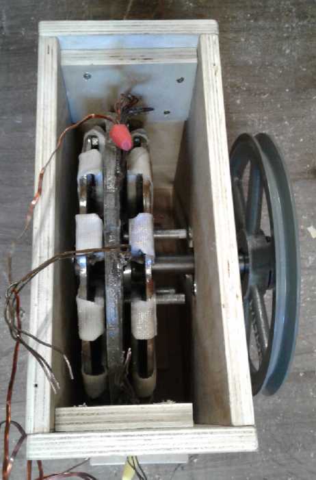
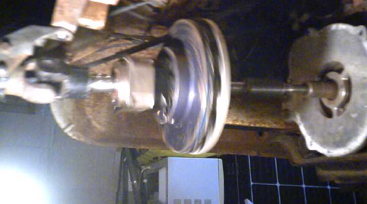
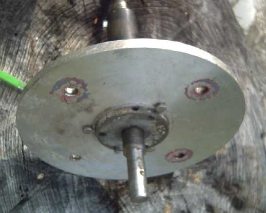
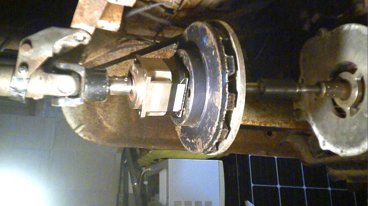 Jury-rigged prototype under truck
RIGHT to LEFT:
* EV Truck's Drive Motor * Kludged Motor Shaft
* Alume Disk (turns with motor shaft) * Magnet Rotor (turns with
planetary body)
* Planetary Gearset (5 to 1 reduction)
* Truck's Drive Shaft to rear wheels, with "U" Joint
* Improvised Hanger/Bracket to Hold front end of Drive Shaft for Tests
Remaining to be measured are the levels of magnetic drag
of these particular coupling rotors, and how warm or hot the alume
disk gets owing to the magnetic slip. But it looks like losses will be
only a very few percent
when underway. What is still needed is an RPM meter on the motor shaft
so the
slip can be measured. (The output shaft RPM can be determined from the
vehicle speed.) The theoretical charts indicate that
it would probably be almost superfluous to lock the two disks together
at higher speeds with any reasonable configuration.
Torque Converter Videos
I made a video and uploaded it to Youtube. But it seemed
people got lost in my long theoretical explanations first part, which I
actually made before I had the truck running, and never got to the
actual tests in the truck. So I did a second video, which was just the
first one without those parts. The viewer will probably "catch on" to
the operation just from
seeing it work.
This torque converter can replace an entire vehicle
transmission.
Its exact operation (to match a given vehicle) depends on the planetary
gearset's design ratio and
the strength of the magnetic coupling.
For the truck I picked a 5 to 1 reduction gearset. With
the 2.2 to 1 reduction in the truck's rear differential, that would
give 11 to 1 - plenty for the motor to start the truck moving. Then as
speed increases and torque drops, the variable torque converter gets
near 1 to 1, so in the truck overall it might be 2.3 to 1, and at 100
KmPH on the highway the motor would be turning just 2300 RPM. Its 10 KW
motor is rated for 10000 RPM peak or 5000 RPM steady, so it's in a good
range with higher efficiency.
Before thinking of the truck, for the Sprint car I ordered
a heavy 7 to 1 gearset, to be connected from the motor straight to the
CV shaft to the right front wheel with no further reduction. 7 to 1
ratio with the 3.6 KW forklift motor should allow the lightweight car
to start moving uphill or from in a pothole and accelerate well. (And
if that's not enough, the ratio can actually increase to up to maybe 10
to 1 with the planetary body turning backward at low speeds.) But as
the speed increases and the reduction ratio drops toward 1 to 1, the
motor is turning the same speed as the wheel (or not much more, say
1050 or 1100 RPM at 100 KmPH, depending on torque required). This suits
this motor which tops out at around 2000 RPM. (Whether a 3.6 KW motor
can actually keep the car, light as it is, moving at 100 KmPH is
another question, but if any drive train arrangement will make it work,
this is the one!
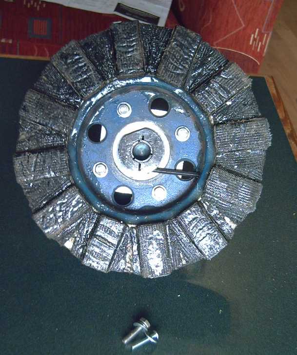
Fabrication & Tests
Having pulled it off the Miles ZX40 cargo truck at the
end of August, I disassembled the planetary drive assembly. I enlarged
some holes on the gearset and rethreaded them for 1/4"-20 bolts.
(#10-32 screws to take the whole torque of the body? Good grief!) Four
holes in the magnet rotor made long ago fortuitously lined up with
those and I bolted then together. Well, that was simple!
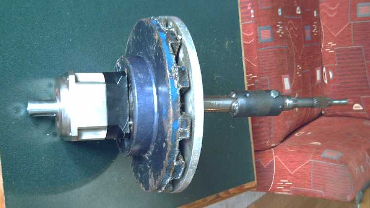
I drilled a hole in the side of the "hat" shaped magnet
rotor to stick an allen key through. Otherwise there was no way to both
mount it on the planetary and tighten the clamp that holds the motor
shaft. Both had to be done "first".
I contrived to put together the alume disk assembly on the
motor shaft using an SDS "taper lock shaft hub" and drilling some holes
in a huge, heavy washer that fit onto its taper, as well as in the
alume disk. I got the disk well centered when I
drilled the bolt holes.
I put the assembly back together with the disks on it and
tightened the motor shaft via the side hole with an allen key and a
flashlight.
 Then I had to
get the truck running again. I removed the
72V lead-acid battery charger. (New chargers?... later.) After that I
made better mounts for the two 36 volt, 120 amp-hour lithium ion
battery stacks and mounted them. I wired them up (in series, 72V) and
in testing found that it was in fact the charger of the 12 volt
battery, a DC to DC converter, that had drained the drive batteries
over time and destroyed 3000$ worth of them. It was turned ON all the
time! It had an "enable" input and should certainly have been turned on
and off with the ignition key. (Thanks, Miles! One of many small
"features" creating big headaches for customers. Small wonder they went
out of business.) I unplugged it - problem solved for now.
Then I had to
get the truck running again. I removed the
72V lead-acid battery charger. (New chargers?... later.) After that I
made better mounts for the two 36 volt, 120 amp-hour lithium ion
battery stacks and mounted them. I wired them up (in series, 72V) and
in testing found that it was in fact the charger of the 12 volt
battery, a DC to DC converter, that had drained the drive batteries
over time and destroyed 3000$ worth of them. It was turned ON all the
time! It had an "enable" input and should certainly have been turned on
and off with the ignition key. (Thanks, Miles! One of many small
"features" creating big headaches for customers. Small wonder they went
out of business.) I unplugged it - problem solved for now.
The motor wouldn't run because the brake fluid was empty
and there's an interlock. (notwithstanding that I had replaced the
brake line to the left rear wheel a couple of years ago. What year
vehicle was this again? 2009? TWO brake line leaks, Really?!?) I filled
the reservoir. From experience I knew I just had to wait.
I connected the
planetary/magnetic drive to the motor and
rear driveshaft under the truck. I made a little bracket to keep the
front of the rear drive shaft from dropping down. Good enough for a
test or two!
3 days later, on the 19th, the brakes worked if I pumped
them, and the motor ran. (It has an "idle" speed/torque if you're not
pressing the pedal.) But the truck didn't move. I put a video camera on
the floor pointing under the truck at the drive, and tried a few more
times. I started thinking there just wasn't enough magnetic force to do
anything. If so the number and diameter of magnetism rotors needed was
going to make the idea prohibitive. Was it another disappointing
failure? But it turned out that the alume rotor had come loose and
wasn't spinning with the motor shaft - just rattling.
So far it was all just a theory. I had only a feeling and
a hope that the magnetic drag force between the two rotors would be
sufficient to make the truck move, and more than very feebly.
That evening I managed to position the disk and tighten
its set screw under the truck without removing the assembly. I started
the camera, got in and turned the truck on.
*** Lo and
Behold! When I pressed on the pedal, the truck moved! ***
Both directions. Smoothly. Without pressing down hard and revving it up
much.
Now the theory was a machine!
Next I tried running it over a couple of pieces of wood.
It had trouble with a 2 by 4 without taking a good run at it,
suggesting the magnetism was a little light. But it was in the
ballpark, and I had just found out that I could make a Halbach magnet
rotor with a greater field from the same magnets, so that wasn't too
concerning. A thicker alume disk (than 10mm) would also increase the
interaction. The mechanism had quickly moved out of the camera's field
of view. So I made a way to mount the camera upside down on the side of
the truck looking underneath, to stay with it as it moved.
The next morning I opened the garage door and backed out.
I came to a virtual stop and then
backed up the shallow slope a little farther. I was pleased that it did
start moving fine going uphill - it wasn't so feeble as the 2 by 4 test
might have suggested. Then I drove in again. I only went 16 feet each
way, but the video showed the variable torque converter principle: as
the motor started, the body of the planetary spun backward, but as the
truck picked up even a little speed it stopped and reversed direction.
(and then spun fast as I took my foot off the pedal.)
The alume rotor was warm, maybe 40-45°C. With stronger
magnetic force the slippage and hence heating should reduce, so again I
wasn't much concerned.
That was it for tests until it all had a proper housing
with two rear steady bearings. But while it was apart, since the
magnetic force seemed a bit light, I would add 6 thin magnets on their
sides to the magnet rotor, to give it the Halbach effect: a larger
magnetic field to the front with a reduced field to the rear. By
September 30th I had split three magnets with the angle grinder and
epoxied them on. I don't think I need to resort to changing the disk to
copper or increasing rotor diameters and the number of magnets, but
there are such places to go if necessary and I don't see how this
torque converter can fail to be practical! (Assuming I build it well
enough, of course.)
The next day (with the epoxy still slightly tacky) I put
the assembly back together. I could feel that it was notably harder to
turn the magnetic rotors against each other except very, very slowly.
I'm not sure it would even want more magnetic force than that.
On October 2nd I was fitting it for the rear bearing
(seeing the wobble, this became two steady bearings - one at each end
of the
planetary) and a housing, and then decided to try just a short move
with the camera running. With the Halbach magnets added the body of the
planetary almost stopped even just "iding", moving slowly - the
planetary's design 5 to 1 reduction. That seems like about the right
amount of magnetic interaction. Above that speed it's going to be
turning more and more with the rest and headed for 1 to 1 reduction.
Barring unforeseen glitches, it's going to work great once the housing
is done!
-----
With the excitement of finally creating an automatic variable torque
converter transmission I didn't get anything done on the "Plastic
Recycling 2.0" project. The oven needs the foam insulation (which
didn't even like 150°C) replaced with fiberglass. One mold needs
the burnt plastic scraped off and the big plate mold (17" x 36") still
needs to be finished. Then it should be ready to produce
plates/tiles/slabs and so on. One project at a time, I guess!
Power Outage Preparedness
After a windstorm in the night, the power went off around
midnight on the 2nd/3rd and was off until the next afternoon. Being
concerned as it had already been off several hours when I first got up,
I started running freezers and fridge, one at a time, from the 36V
battery system with inverters.
The 600W inverter that I had tested to run the smallest
freezer with, this time would alarm and quit. Humpf! - a "nominal
36VDC" inverter that seemed to cut out when the voltage fell to about
35.9? - gee, thanks! I got out the 2500W one and more extension cords
and got the freezer going. Later I connected an unused ground wire in
the #10-2 cable to the DC outlet I had plugged the 600W inverter into,
to double up the minus wire, and after a couple of tries got the 65(?)
watt freezer running. Two freezers, maybe 65 and 115 watts, plus the
two inverters themselves brought it up to 210 watts.
It was dull and raining and the charge controller wasn't
even keeping up with one freezer. Part of the problem was the long,
thin charging cord to the batteries (#16 AWG extension cord). Using the
(2500W) inverter to power the soldering, I replaced that with a
considerably shorter #14-3 house wire cord, in which I doubled up the 4
wires (counting the bare ground wire), giving an effective #11 AWG two
wire cable. That helped perk up the charging. Then I turned off one
grid tie inverter and with alligator clip leeds, connected its 1000W
(my old 2012) solar panels on the roof in parallel with the three
panels on the lawn, which were probably in tree shadows as well as the
heavy overcast. That perked it up to 200 watts or so - almost keeping
even. I'm sure that wasn't optimized output from the 9 panels. (And
shows the weakness of having three separate solar panel installations
when wanting one maximized DC output.) In mid afternoon I switched from
the larger freezer to the refrigerator - also about 115 watts as long
as the 400W defrost coils don't come on - and got it cooling again.
Then finally the mains power came back on.
Switching power back and forth between 4 units would wear
thin pretty fast, and carries the danger of accidently leaving one
unplugged and having food thaw out - or simply running out of battery
& solar power, especially in winter. The fridge with its 400W
defrost coil could really be a killer. Hopefully if the power does ever
go off for a long time, by that time I'll be down to the two very small
65-75W freezers, having reduced the amount of frozen food I have. (Why
do I keep buying more? But they're not as full as they were.) One of
them will be turned down (up?) until it's a chest refrigerator instead
of freezer. The higher power units will be turned off.
While the power was out, I kept flipping on the light
switch every time I entered a room, of course to no effect. There is no
question
but that there will be much inconvenience if the power does go out for
a long time, even with all the prep so far. I hope others are doing
things to be ready, because the weather keeps getting more chaotic
causing vast crop failures, civilization is failing in front of us and
more and more we see some hard years - maybe a couple of decades -
coming. The social changes will be immense.
In
Passing
(Miscellaneous topics, editorial comments & opinionated rants)
Proactive
Approach
to
Democracy
Interesting quote under a video
comment. Seems like how many "underhanded" projects in "democratic"
societies have been prosecuted for a century or more.
"We decide on something, leave it lying around and wait and see what
happens. If no one kicks up a fuss, because most people don't
understand what has been decided, we continue step by step until there
is no turning back. -- Jean-Claude Juncker, President of the EU
Commission 2014-2019
First, people will only "kick up a fuss" if what's been
decided seems to be against their best interests. But they may not
anyway, not because it's not understood, but because it's not worth any
one individual's time to take time and money out of his life to "kick
up a fuss" and fight a bad move that only affects him (along with
everyone else) just a little.
And if it's an agenda being diligently pursued, people can
fight and win the case, and then when everyone not invested in it and
not being paid heaves a sigh of relief and moves on, the proponents
just bring it
back in slightly different form a year or two later. The fight has been
knocked out of everyone, and no one has more energy to rise up again to
protest.
So, adverse decisions and actions pile up and make things
a little worse bit by bit and only over decades do people start to
think "Hey, society wasn't anything like this when I was young!"
This is a huge problem with today's essentially negative
approach to everything. No one except the people at the very center of
the governing structure has any positive power or influence to effect
changes or even to provide input. Everyone else can only protest -
another negative approach. The talent, leadership and organizational
energy from the whole of the general public - from the most thoughtful
and caring citizens, those knowledgeable in countless different special
areas - is cast aside, wasted.
We need to switch to a positive, proactive approach.
As I've suggested before (and am sure to do again), people
must form "ad hoc" organized local teams or committees, often outside
of all existing institutions and organizations, to study in depth
something they feel is important to them. If practical (except for
unique local issues) they then link by internet with similar groups in
other locations, and together present well thought out, well researched
and clear recommendations to government. Then government acts as a
coordinating agency to enact what these most interested and intelligent
members of the public have together agreed upon, issue upon issue, as
the members of the many and various teams most interested in each
aspect of organized society find important to themselves or to society.
And if these teams perhaps continue to meet for some time,
they may measure the results of their original deliberations for
potential revisions. Or a new team may be formed to look at it anew.
This sort of review of results of often ill-conceived legislation
passed today just doesn't happen, and it is rare for any legislation,
whatever its results intended and unintended, to be repealed or
improved.
We might take the examples of IEEE and ASHRAE (Institute
of Electrical and Electronic Engineers, and the American Society of
Heating, Refrigeration and Air conditioning Engineers. ASHRAE groups
hold local dinner and other meetings and events. They are
voluntary, non-government, non-corporate bodies - just people
associated within a field - yet they set standards in the electrical
and
HVAC fields which are generally adopted by governments everywhere
without political comment, and
they amend them when they need modifications. Can we not extend this to
many other areas of interest - professional, economic, social, health,
educational and cultural?
There are of course further aspects to the reform of our
societies, but I see them as resolving themselves in the future. Some
can be addressed via the internet, but so far have not been.
One should be able to readily find the background
and real views and attitudes of all those running for an office at one
web location, not just hear the opinions of opinionated mass media, who
more and more today themselves have a stake in the outcome and can't be
relied on to provide information that is in any sense impartial or
fair. Today we have duplicitous "politicians" who say one thing on
camera to the public and something entirely different to each different
audience - to power brokers behind the scenes. They often have no
intention of doing what they told the public. Such behavior should be
exposed. What stances have they taken in previous issues? Do they make
decisions contrary to citizen groups' wishes? Are they giving away
public assets to their supporters? Do they have a criminal record?
Honesty and sincerity should be assets to a politician, not liabilities
or even disqualifications as they are today.
Special interest lobbying should be become obsolete as
organized citizen groups bring more balanced views on each issue. The
needs and wishes of the public and society at large should prevail over
special interests.
All voting should be by choice ranking (AKA "transferable
vote" and other names). While one can pick holes in any voting system
if one tries,
ranking the choices and recounting as many times as necessary (or
having
runoffs) to find the 50% majority consensus is the only one I've seen
where there is never a reason to vote any way except according to one's
true desires. No "strategic" voting for something you don't like best
in order to prevent something even worse. No voting for a "party"
rather than the best qualified person. (More aspects to our systems
being essentially negative.) In general today's politicians and
political party managers don't like choice ranking because it is also
the system least susceptible to manipulation and to big political party
hegemony over the electoral processes. And of course the voting system
must be honestly administered. Democracy is over when it isn't.
And of course the three branches of government should be
separated. One should vote for a civic, state/provincial and national
chief executive separately from one's legislative representative. And
many reforms could be suggested for the composition of our legislative
bodies. They should represent a cross section of the whole of society,
not be a bunch of clones beholden to a particular party line or
philosophy.
I should shut up here (if not sooner) - I could go on with
these known ideas largely kept from us by today's politicians and
political systems. The key new idea which is being
presented to us all is that of having organized peoples'
committees/societies/groups/teams, linked together by internet to form
national consensuses on all manner of national interests, and these
clearly expressed desires coming from the public being carried through
to becoming the policies of the government, which would then much
better represent the people who elect it. Government of, for and by
the people, in well organized channels.
Asteroid
Dimorphos:
Ahrrrg, Monochrome Again!!!
NASA decided to test the idea of diverting the course of an asteroid in
case one is ever heading too close to the Earth by crashing a space
probe into one. They chose one called Dimorphos, orbiting a larger one
called Didymus. (the only asteroid with a moonoid?) It took a series of
images as it approached at high speed. Thus we have a few very detailed
images of this asteroid from close ranges. The scene below is clipped
from the "penultimate" image, the last one before the crash. To a
casual glance - and I'm sure that's all anybody at NASA or JPL will
give it - the surface is a jumble of rocks.
I was pretty sure the orbit of this pair was too close to
the sun to host the sort of very alien airless world life detected
(even if no one seems to recognize it) on Ganymede and other airless
worlds in the Jupiter and Saturn regions, and of which a seed was
captured by a very high altitude balloon searching for alien life
("panspermia") in 2015 (TE News #85).
And
yet,
the
scene
on
close examination doesn't seem to be lifeless
rocks.
So here is the original monochrome image, and below it one
I've colorized to highlight a few of the features. (The brightness of
each feature is unchanged, but the gray has been shifted in hue, eg
++green,-red,-blue.)
Especially the green object with folded down 'jagged' edges has every
appearance of being a leaf. By their shadows, yellow objects especially
seem to be flat and off the ground rather than boulders, also
suggesting leaves. I thought the red objects looked like leaves coming
from central roots. and there are some things that look like striped
stems. There's
more of the same in the full image, but I thought this area was a good
illustration. (Consider in viewing that gravity is next to non-existent
and the contrast between light and shadow is very high because there's
no atmosphere to scatter light.)
And now I go back to my decades long lament: WHY oh WHY do
NASA, JPL et al think that monchrome images show us enough and that
color images are somehow "unscientific"? The only craft that have gone
to the
outer solar system that had proper color cameras were the Voyagers in
the 1970s, and they opened our eyes to many fascinating new worlds.
(And they only got color because of a couple of left-over color cameras
from
the Mariner mission to Mercury!) Oh wait... and the recent "New
Horizons"
probe to Pluto, which also showed us a fascinating sphere that
monochrome wouldn't have done justice to. But there are still no color
images below "continental scale" of any outer solar system world.
Billions of dollars for space missions and they can't even
throw on a 39.95 $ color camera?!? Again I am reminded of a monochrome
"picture of a cow" that our class was shown in high school. It looked
like a
piece of abstract art. Blotches of white and black. I was trying to
visualize some artist's abstract rendition of a cow. Only after every
feature was carefully pointed out to me (and just as the teacher was
snatching it away from me) did I suddenly recognize that it was a
perfectly clear, sharp photo of a cow standing in front of a fence!
(Other students had similar reactions - that sudden "OOHHH!") A color
image would have been perfectly clear and unambiguous.
Likewise, a color image would have immediately revealed
the true nature of this scene. this and many other planetary images in
which we seem to be blind to their true nature in the pathetic
monochrome renderings we've been handed.
Well, as my mom once said "Scientists are blind." She
should know. My dad was a mycologist (and often "blind") and they
were in the university's social circles/faculty club so she knew plenty
of them.


How
Famines
Develop
Rapidly
According to Michael Yon, From Video: "You're Going to See a Lot of
Starvation!!! | Jordan Peterson 2022"
https://www.youtube.com/watch?v=GdtWB8sE4q0&ab_channel=JohnnyBigger
(The above video was excerpted from another much longer video by Jordan
Peterson:)
" Cometh the Horsemen: Pandemic, Famine, War | Michael Yon | #274"
https://www.youtube.com/watch?v=R7gAEkzIgvw&t=490s&ab_channel=JordanBPeterson
Yon:
When people are hungry within 48 hours they're going to hit the
streets, right?
And they'll start robbing the stores. Then they'll start robbing the
trucks and the trains and the boats, and so then supplies stop going.
Then governments always start taking food from the farmers.
[<snip> ...and control the food.] So people start robbing from
the farmers as well, right?
And then the farmers say, hey, I'm either bankrupt or I'm not making
any money. And so the farmers stop farming. So that's how you see we
get into the second season of this, right?
And so the famine creates more famine, just like fire creates fire.
And as [peoples'] nutritional, you know, resources diminish, so too
does their physical resiliance. And now they're open to disease. Many -
if not most - of the people who die in famines actually die from
[<> ...diseases] -- they call them "famine fevers".
<> ...and these sorts of things often lead to more war, right? So
it's a recursive sort of, you know, the factors just keep... <>
it's almost a fission reaction, right?
Jordan, I would not be surprised if by 2025 a billion people aren't
dead. I mean, we're really headed into the most epic famines that have
ever happened in human history.
======
Peterson thinks Yon's predictions are dire, but Yon isn't looking very
far down the road thinking only to 2025. As we are supposed to hit 8
billion people before the end of this year with climate mayhem and
failed crops just getting underway, digging out the dregs of the
remaining petroleum and other presently needed natural resources and
with the present people in positions of leadership in most nations in
it for themselves or actually bent on destruction and depopulation.
Probably around 6 billion will be gone before 2050. Well, that's almost
30 years with aging populations through the civilized parts of the
world, so an awful lot of us were or are going to die of old age
anyway. Still it's not going to be pretty. We should foster and
preserve all of nature and ecology that we can in the coming decade or
two. What if deer, kangaroos, wildebeest, elephants and so on (not to
mention the predator species that eat them) become extinct in the
desperate human hunt for food?
In a "steady state"
condition the world might support 3 billion people, but it's going to
dip way down under that owing to our degradation of the environment and
ecology. Some people think one billion or even fewer, but I expect
it'll be closer to two. (And after all according to official figures
it's just 95 years since we first hit 2 billion people.)
But again this is all part of Christ Michael's "Correcting Time" plan
to rehabilitate the few planets whose spirit leaders followed Lucifer
into
rebellion, now that the Lucifer Rebellion has been terminated and the
unrepentent arch rebels eliminated by the Ancients of Days. (...in or
about 1984 Earth time, and with their own agreement/acceptance that, as
they were unwilling to repent, there was no further place for them
anywhere in the universe.)
With better (human) leadership and global cooperation,
this die-off might be put off until the world was at 10 billion or more
people but the sooner it happens, the more will be left of the world's
ecology, the more species will remain and the more people will be left
by the end of it. If it was to hit 10 or 11 or 12 billion before the
population crashed, little would be left of nature and ecology and
those remaining (if any) would probably be small
isolated groups of people eking out meager livings, all fearing each
other and unable to resume any sort of global civilization. (It reminds
me of a bit in Matthew 24: "If those days had not been cut short, no
one would survive, but for the sake of the elect, those days will be
shortened." These would seem to be those days.)
With a collapse from the present population, a new and
better civilization can and will rise from the ashes of the old. People
will have learned a huge lesson that this world can only provide a
good quality, prosperous life to so many people at a time, without
overshooting
the global carrying capacity. And with good birth control now available
only wanted children will be born into good (and small) families from
where they will be raised to be productive and contented human beings
and at last population and ecological overshoots (the sad endings of
dozens of previous human civilizations) will be ended. So will wars.
Techniques of obtaining "free" energy which have been
withheld from us so far owing to our social and cultural immaturity and
the immensely destructive uses to which it could be put, will be
rediscovered and adopted, freeing the world from petroleum resource
dependency and depletion. And sometime in the coming decades in the
midst of our crises, a new Divine Son, the avonal son Monjoronson, will
appear. He is in fact already present on or about the planet as a
spirit being but he will not materialize until he will be welcomed.
Unlike Jesus he will appear as an adult, and he is expected to stay on
Earth for 1000 years and help guide our development into the beginnings
of a
golden age of Light and Life. (I'm sure we need all the help we can
get!)
Satellites
or
Drones?
On the evening of
the 13th at about 21:30-21:35 PDT, I happened to be outside and I saw a
string of lights, "stars" traveling across the sky, one after another
in a
perfect straight line. I counted 32. They seemed to go from the
west-southwest to the east-northeast, passing a
little to the southeast of me, seemingly very high up. They were moving
too fast to be satellites. At first they might have been every 3 or 4
seconds or less. One light in the line (5th or 6th one?) was missing,
making a double length gap.
Gradually they became more spread out, passing by maybe every 7 or 8
seconds. or longer. From where I was they appeared from behind a tree
branch, one after another. I thought maybe I heard jet engines, but it
was
high tide and with the crashing ocean waves sounding covering
other sounds, I really wasn't sure. But airplanes don't follow each
other in a straight line anything like that closely.
The direction said they started over the Pacific Ocean
somewhere (or Asia?) and that they were headed toward the Northwest
Territories... or over the pole and beyond toward Europe or Russia. I
don't
know what they were, but in today's political climate this unique event
was disquieting.
Then on the 15th I read about US Army Conducts Drone Swarm
Exercise with Armed Quadcopters.
(Zerohedge.com Sept. 14th, 8:20 PM) There were 40 drones in that - just
about the same number I saw. So I thought probably this was another
drone swarm exercise, with another batch of the same drones. So they
would have been lower and slower than I had thought, with the loud
waves masking their noise? I expect then that they flew from a ship
nearby off the coast and weren't going as far as I imagined.
Coming after Biden's inflammatory speech with the blood
red
background and marines standing behind him, I fear reader comments
under the article are right, which suggest the drones are going to be
used against Americans - that would doubtless be any and all who have
expressed criticism of the 2020 US elections and present government - a
new "night of the long knives" to silence thousands of critics all at
once. Before the 2022 US elections in November. To save democracy from
MAGA terrorists (adverse votes). Doubtless they have been compiling a
list. Canadians won't be left out I'm sure. Everybody has a cell phone
and their location can be pinpointed at any time. Sudden death without
warning from the sky. Think communist purges; Argentina, Chile,
Pinochet.
Well, some are saying these fast-moving in-line objects
are Elon
Musk's "starlink" satellites. They certainly followed an undeviating
straight line. Even if they are I will not retract the
above paragraphs. I will be very relieved if I'm wrong!
Smol
Thots
* I heard somewhere that humans account for 32% of the total land
animal mass on the planet.
Livestock makes up 67% and wild animals 1%. The percentage of wild
animals has plummeted in recent decades. (I suspect this statistic only
includes mammals - it wasn't specified.)
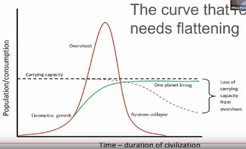
* Someone made this chart of the
"carrying capacity" of the Earth. (See Collapse in a Nutshell", youtube
channel "TheGreatStory" by Michael Dowd) At the left we start with a
low population, which gradually grows.
Then there are two scenarios. With the green line, the
population wisely stops growing before it gets too large. No more
resources are consumed annually than nature can replenish.
With the red line, the population continues to grow. When
it becomes too large it starts consuming more resources than are being
replenished, and starts degrading the ecology to sustain itself. When
it has finally used
up all the resources, or at least one or more necessary resource, there
is famine and the population crashes, and afterward the degraded
environment (dotted slope) can't support as many people as it could
before.
While illusrative, I would object to some of the details:
(1) The population on the left was never "minisule". If the North
American natives had an estimated 50 million hunter-gatherer people
before the Europeans came, why would the whole Earth only have had 10
or 20 million for most of a million years as most scientists seem to
suppose? Surely it (Asia, Europe, Africa) would have supported closer
to 500 million primitive hunter-gatherers?
(2) The "overshoot" looks almost like a part of a sine wave. In fact,
collapses of civilizations are generally extremely rapid compared to
the gradual growth and the line should go down very steeply, practicly
straight down.
(3) The "loss of carrying capacity" should drop during the
overshoot, after which it should (we hope) begin to recover, which
isn't shown. There is some "point of no return" (like making
most species extinct and cutting down every last tree on Easter
Island), and a "point of very, very slow return" (like the present
harsh desert the overpopulating Anasazi people made from a pine and
juniper forest). But short of those, it should gradually recover after
a population crash. I expect that will be the future scenario, although
we are losing species at a great rate at the present time.
Many have estimated 2 to 3 billion people as the maximum
carrying capacity. I lean toward the lower figure after the crash
(others say still lower) and the upper once things improve again, but
it is certainly a maximum. (According to one chart, we originally hit 2
billion in 1927 and 3 billion in 1960. Then 4 billion in 1974, 5 in
1987, 6 in 1999, 7 in 2011, and are expected to hit 8 billion this
year. And over half this bloated population can only eat thanks to
mining non-renewable resources which are now becoming quite depleted.
This is a
runaway train that can only end in a trainwreck.)
* It's interesting to click on youtube
on a video of some old celebrity. Soon you are seeing video suggestions
for all kinds of people you haven't heard anything of in decades - or
some who were famous before I was born. (Colonel Saunders
was a real person? Looked just like his picture. Virgil Earp, Wyatt
Earp's nephew, talks about being
a sherrif in the old west? Gasp!)
* The UN and the West were lamenting that because of the fighting in
Ukraine, grains from that country weren't reaching nations where
starvation is reaching epidemic proportions - North and Central Africa,
Pakistan, Bangladesh... Russia kept saying that for humanitarian
reasons it wouldn't stop grain shipments from Ukrainian ports and would
even lend minesweepers to help clear mines laid by Ukraine around their
own ports. Finally an agreement was worked out with Turkey as an
intermediary (I presume to ensure that the ships weren't being used to
smuggle weapons into Ukraine), and the grain began to flow.
Of the first 80+ shiploads of grain leaving Odessa, all
but two went to European ports or to USA. Only 3% of the grain went to
the starving countries cited as being the reason Ukrainian shipments
were desperately needed. Is that pure hypocrisy, or is Europe, without
having admitted it, also in desperate need of grain? A desperate Europe
can doubtless afford to pay more for it than desperate Egypt, Central
Africa, Pakistan and the Middle East.
Sure enough, TFI Global had a headline on Youtube on the
14th, "Europe is Staring at an Intense Food Shortage".
* Furthermore, Russian grain shipments were supposed to be
un-sanctioned too as part of the deal, but so far they haven't been.
* As Ukraine counterattacked and took areas in the undermanned Kharkov
region, residents fled with the retreating Russians and headed across
the border into Russia, fearing reprisals from the Ukrainian forces or
administration - and no doubt future fighting in their towns - and of
possibly being conscripted into the Ukrainian army.
* RT-Russian has a map of Russia full of green dots showing
places/homes where Russians have volunteered to host refugees from
Ukraine/Donbass.
* Putin said there would be referendums in Lugansk, Donetsk,
Zaporizhzhia and Kherson to see if they want to join Russia. People in
these areas wanted them - have wanted them for some time. The USA said
in advance they wouldn't recognize the results regardless of anything.
Zelensky says if anyone participates
or votes in them, they will face 5 years in jail. Congratulations! You
have ensured a virtually 100% "Let's join Russia" vote. Who would vote
to be part of Ukraine and face prison time if they win the vote? Any
slim chance that Kherson or Zaporizhzhia might vote to stay in Ukraine
just went out the window. [29th] International observers were there.
The results came in. Only in Kherson was the vote under 90% to join
Russia at 85%. In Donetsk it was over 98%. If Ukraine had treated its
own citizens with common respect, no doubt the results would have been
quite different, or the referendums would never have been needed.
I am not in favor of the limited choices offered in the
referendum: Join Russia, "Da" or "Net". But if more choices were
offered it should have been on a choice ranking ballot. For example,
Donetsk could have been offered "rejoin Ukraine", "remain an
independent republic" (or perhaps "form a new republic of all the
Russian Ukrainian regions"?) or "join Russia". In this case I have
virtually no doubt the end result would have been the same, but we
might have learned more about the more exact sentiments of the peoples.
Some might have preferred to remain independent, and the less than 2%
"Net" might have become, say, 15% whose first choice might have been
for an independent "Eastern [Russian] Ukraine". (In Kherson,
"independence" might have been very popular.) And with more choices
revealing more about the real sentiments of the affected people, it
would be harder for the West and Ukraine to scream "Not Fair, Not Fair!"
* Putin announced a partial mobilization of Russian forces, calling up
of reservists, following on the retreat from Kharkov area. The former
head of defense of the Donetsk People's Republic (DPR) (whose name I've
forgotten) said right from the start that Russia hadn't committed
anything like enough troops for their operation to succeed. Looks like
he was right.
I guess if you're fighting with fewer forces
than the enemy but great equipment and tactics, you can win your
attacks even
against fortified positions and inflict great damage, but still not be
strong enough everywhere to hold the lines against a concentrated mass
attack at some point(s) along a long front. As some commenters have
noted,
ending the whole thing faster via increased force would result in less
pain (and lower costs) overall and for all. The retreat has been called
a sign of weakness and failure on Russia's part, and this is apparent.
If they didn't have adequate forces to hold the ground they took or at
least a reserve to quickly counterattack, they should have been
recruiting earlier.
It can also be said that in war, what you least want or least expect
the enemy to do is usually what they do. Churchill (somewhere in his
WWII memoirs) said something to the effect that wars consist largely of
a catalogue of blunders and disappointments. OTOH, even this small
mobilization of reservists has caused apparently considerable commotion
inside Russia.
 * As Europe
heads into an extreme energy crisis that is crushing their entire
economies, Putin reminded them all they had to do to end it was drop
the sanctions and open the Nordstream 2 pipeline, already built and
sitting doing nothing. All they are doing by supporting Ukraine is
prolonging the fighting and causing severe crises for themselves. (Soon
after that the Nordstream pipelines were blown up!)
* As Europe
heads into an extreme energy crisis that is crushing their entire
economies, Putin reminded them all they had to do to end it was drop
the sanctions and open the Nordstream 2 pipeline, already built and
sitting doing nothing. All they are doing by supporting Ukraine is
prolonging the fighting and causing severe crises for themselves. (Soon
after that the Nordstream pipelines were blown up!)
* Why Europe continues to fight the US or international "deep state"
proxy war is beyond me. Especially puzzling were the unexpected moves
of Sweden and Finland to join NATO. I think I have the answer: bribery
of or threats (or both) to top officials including the leaders in those
countries. Maybe the old "I have a wad of money in this
pocket to do it our way or a gun for you and your family in this one.
Which do you choose?" trick. Anyway some kind of heavy pressure from
USA. Nothing else makes much sense to me. The idea that they are
suddenly terrified of an attack from a Russia that seems quite bogged
down just with Ukraine which they had good and explicitly stated
reasons for attacking, seems ludicrous.
* The fact that Europe has become so
reliant on Russian methane (AKA "natural gas") and oil is probably the
best indication of how far down the road of using up these
non-renewable energy sources the world has traveled, as well as to how
high the population has bloated. "Peak oil" is way behind us. Without
the Russian contribution,
there doesn't seem to be enough readily accessible fossil fuel anywhere
in the world to meet all the needs. OPEC raised its "production
cap", but it brought little more oil on line. If there even is
more, new extraction and refining facilities need to be created in
order to deplete the remaining reserves faster.
* Those running Washington DC who have left the US southern border wide
open as millions of unknown migrants come flooding in - and even flown
them in by the planeload - destabilizing the country like never before,
don't seem at all to like having governors of southern border states
shipping even a few of them - drips in the bucket - into the northern
states where they live. They're calling it "criminal acts".
("We welcome illegal immigrants but they can't stay here!")
* I feel sorry for those migrants as well as the Americans being
overwhelmed by the flood. The USA is falling apart before our eyes.
They've been promised more than US citizens are now able to procure for
themselves or will be able to give them. Will they not all soon be
starving, the population and the migrants alike? It seems almost like a
trap.
* Near the end of the month both Nordstream methane gas pipelines were
blown up under the sea. Now it doesn't matter what Germany decides
about maintaining sanctions against Russia or not: Europe is screwed.
Germans and other Europeans are going to freeze to death this winter.
They will burn down the remainder of Europe's forests in quest for
firewood. Countries will collapse into chaos.
The USA is selling liquified methane ("LNG") to Europe at
exorbitant prices. Biden, in mid February, publicly threatened to "shut
down Nordstream 2" "if Russia attacks Ukraine" and to a question of
"How?" just said
"I promise you, we will do
it." Few are buying the story that Russia blew up its own 20 + 15
billion dollar pipelines... the "plausible deniability" is implausible
and the escape goat is escaping!
ESD
(Eccentric Silliness Department)
* Real versus Imaginary Numbers:
McRancher: "Yessir, I have over 50 head of cattle on this ranch!" --
McJealous: "Ya? Well, I have 5000 head of cattle on my
ranch!"
* Q: Why is it that whatever you're looking for is always in the very
last place you look? A: Because after that you stop looking.
"in depth reports" for
each project are below. I hope they may be useful to anyone who wants
to get into a similar project, to glean ideas for how something
might be done, as well as things that might have been tried, or just
thought
of and not tried... and even of how not to do something - why
it didn't
work or proved impractical. Sometimes they set out inventive thoughts
almost as they occur - and are the actual organization and elaboration
in writing of those thoughts. They are thus partly a diary and are not
extensively proof-read for literary perfection, consistency,
completeness and elimination of duplications before
publication. I hope they may add to the body of wisdom for other
researchers and developers to help them find more productive paths and
avoid potential pitfalls and dead ends.
Electric
Transport
Variable Torque Converter with Planetary Gear: a Magnetic Method
(It Works Great!)
(Plus Miles ZX40 EV Truck Renovations)
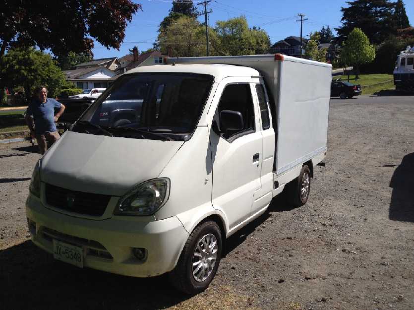 The Truck (in 2016): The test
vehicle for the
torque converter
The Truck (in 2016): The test
vehicle for the
torque converter
Variable Torque Converter Project
Review
As I recall I started the "variable torque converter"
project in June 2009 when I realized that the "Electric Hubcap" axial
flux BLDC
motors I had started creating the year before couldn't have the torque
to start a car rolling directly coupled to a wheel, but couldn't safely
or efficiently
rev up to higher thousands of RPM during high speed travel if they were
geared down a lot. Axial flux BLDC is the most efficient type of
motor in various EV operating conditions including in regenerative
braking, but they're most efficient at lower RPMs, eg, under 2000. And
at lower RPMs rotor inertia isn't a serious problem. A continuously
variable automatic variable torque converter sounded like the ideal
solution, and I was sure there
had to be some relatively simple way to make a good one. The
designs
others have come up with were anything but simple, effective and
efficient. They include:
* The fluid torque converter (anything but efficient and with only a
limited range of ratios)
* special steel belts and cones (Honda cars)
* a V-belt and centrifugal varying pulleys (snowmobiles, etc.)
* Constantinesco's 1920s variable pendulum mechanism that worked well
but put heavy stresses on the materials (apparently wore out fast).
* an amazingly complex gear system that had to have a second motor spin
a small gear to vary the main ratio (AFAIK only a sample prototype was
ever made)
* Toyota's dual planetary gear system, which again was driven by two
motors and an engine rather than by a single motor - complicated.
In fact I was sure there must be multiple ways it could be
done. But I had
no idea what any of them might be. Apparently neither did anyone else,
or someone would have already built something better. On actual
examination good solutions were elusive. So I seemed to be
(as I often am)
in uncharted territory.
While I blundered down many blind alleys, I consider that
some of the ideas in 2009, 2010 and beyond had merit. They were
components of potentially good ideas. My first idea of
a magnet rotor driving an alume disk on the car wheel by magnetic drag
had the essential "magneticly variable" part, but it started with 1 to
1 gearing that didn't actually magnify the motor's torque when the
wheel was turning slower than the motor.
The idea of slipping a planetary gear body backward to
increase its gear ratio was also a good one, but I was trying to drag
it to a stop as speed increased. The idea was it could have an
"infinitely" high ratio dropping down to its designed ratio. But I
wasn't
actually getting that, mostly just making heat. It could have worked by
having a generator slow the body and return the power the batteries,
but that seemed too complicated to build. I didn't come up with
the idea of having it slip forward against another of its own
gears to reduce the designed ratio until much later. Then I
finally
realized that if it
could be made so that all the elements spun in unison, it would start
from some higher ratio and finally at highway speeds all elements would
spin at or near 1 to 1. This was a key concept. But I still hadn't
combined the ideas. And the fabrication situation was complicated by
wanting to drive the chain I had made connecting to the differential of
the Sprint
car, which was of course off to the side rather than in-line, using
what is naturally an in-line mechanism. Putting the "in line to wheel"
planetary
gear in the Chevy Sprint (seemingly an unrelated side project) started
also lining
things up in my head.
Finally I realized that the plan from a very few years ago
for combining a planetary gear with all elements spinning and the big
centrifugal clutch should work with the new in-line drive in the
Sprint. But the project got put off by difficulties of construction and
layout,
and other events and projects. And the big clutch was mechanicly
cumbersome and I was pretty sure it would be noisy and would wear out
quickly - but if it did the job, it would be worth it. It could be
improved later for production if it made for a good variable
transmission.
Then just last month (August 2022) I thought of using a
planetary gearset the same way (all elements spinning) but with magnetic
drag rotors between two elements in place of the centrifugal
clutch. The potential quietness and smoothness of operation with no
mechanical wear were much more appealing. I searched around my shop and
storage and soon located all the needed components. Nothing had to be
made from scratch and nothing had to be ordered. (Wow!) And then I saw
that there was room under the Miles ZX40 electric mini-cargo truck to
install the whole mechanism, and furthermore to do so utilizing what I
had already fabricated for the truck just to put a fixed 5 to 1
reduction planetary
gearset on it. So it not only seemed like a highly promising design
concept, but it also looked like it should be a rapid fabrication to
the point of initial prototype testing instead of a long, drawn out
project that would get put off and put off again by other priorities.
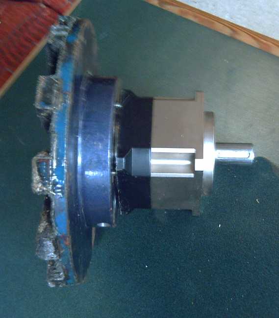
 Jury-rigged Planetary-Magnetic
Torque Converter
Jury-rigged Planetary-Magnetic
Torque Converter
being tested under the truck
And within a month I've
proved it works. In retrospect a design quite plain and simple, where
in the
future people will look and say "Of course that's how it's done!" Yet
no one else has ever come up with anything like it, and it took me over
13 years. My vague 2009 variable torque converter conception was
finally vindicated in tests on the 19th and 20th.
Videos:
As per the theory, in the
brief actual tests in the explanatory video, especially the last test,
one can see the body of the planetary gear start to turn backward, then
slow to a stop and reverse direction (adjusting the "gear ratio" on the
fly) as the speed and torque changes. More work is of course required
to make it practical and roadworthy, but the use of one highly
efficient automaticly
variable gearset with magnetic rotors to replace an entire vehicle
transmission will allow
more optimized electric drive motors to be used, operating in their
optimum RPM range at all vehicle speeds. This will reduce vehicle
energy consumption, reducing required motor size and power and
increasing range, and hence improve the entire automotive industry.
AFAIK no one else else has come up with such a fabulous
and simple design. The result is surely worth all the years it took to
get
here. Of course it wasn't my only project in all that time. Sometimes
one experiments and sometimes one does other things and waits upon
inspiration and a more advanced concept before proceeding. But without
the effort of trying things out and pushing the bounds to flesh out
possibilities, the inspirations for how to go farther won't come.
The Fabrication
I got something of a mental
block about starting building this. Probably too many disappointments.
over too many years. But I told myself "a little bit every day and
it'll be done before I know it!" (Then I can start on installing
batteries and chargers to get the truck running again.)
[4th] I had previously pulled the gearset and shaft out of the truck.
Now I pulled the extended motor shaft off the planetary.
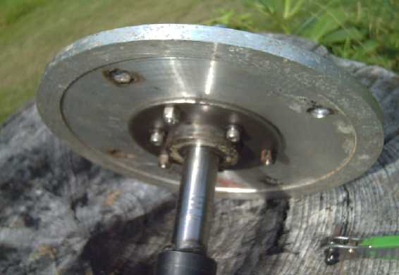 [5th] I fit together
"assembly #1", the alume disk on the motor shaft.
It's a very long shaft taking up the length of the original
transmission on the truck, with one end to fit the motor socket splines
and the other to fit into the planetary gear input (sun gear). I was
"lucky" how well these parts fit together, except I've tried to
"standardize" my experiments with 1.0" shafts and I bought those
washers exactly because they did fit on the taper of SDS taper lock
hubs. So only the
"almost" fit of the alume disk over the large part of the SDS hub was
completely fortuitous. I turned the 1" shaft down (long ago for
something else) a
bit much in the area where the hub must sit, but it should be close
enough, and again it was fortuitous that it needs to sit right where it
was turned down, with maybe 1/4" sliding room to play with magnet gap
adjustments.
[5th] I fit together
"assembly #1", the alume disk on the motor shaft.
It's a very long shaft taking up the length of the original
transmission on the truck, with one end to fit the motor socket splines
and the other to fit into the planetary gear input (sun gear). I was
"lucky" how well these parts fit together, except I've tried to
"standardize" my experiments with 1.0" shafts and I bought those
washers exactly because they did fit on the taper of SDS taper lock
hubs. So only the
"almost" fit of the alume disk over the large part of the SDS hub was
completely fortuitous. I turned the 1" shaft down (long ago for
something else) a
bit much in the area where the hub must sit, but it should be close
enough, and again it was fortuitous that it needs to sit right where it
was turned down, with maybe 1/4" sliding room to play with magnet gap
adjustments.
 Before I finished I roughed up the end of
the shaft with
the grinder because it was so prone to slipping, the planetary having a
socket with just a clamp
with one screw and no key slot or even set screws to affix it more
securely.
Before I finished I roughed up the end of
the shaft with
the grinder because it was so prone to slipping, the planetary having a
socket with just a clamp
with one screw and no key slot or even set screws to affix it more
securely.
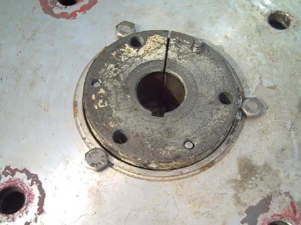
 [6th] I had to drill a hole
in the side of the "hat" on the magnet
rotor. Otherwise there was no way to both mount it on the planetary and
tighten the clamp that holds the motor shaft. Both had to be done
"first" - unless the allen wrench could go in through the hole. I went
into town to find some hardened #10-32 machine screws. They only had
the same cheap ones I already had. I finally decided they were
ridiculously small for the amount of torque they needed to withstand
and drilled out the holes to the same depth and tapped them for 1/4"-20
bolts. That's much better.
[6th] I had to drill a hole
in the side of the "hat" on the magnet
rotor. Otherwise there was no way to both mount it on the planetary and
tighten the clamp that holds the motor shaft. Both had to be done
"first" - unless the allen wrench could go in through the hole. I went
into town to find some hardened #10-32 machine screws. They only had
the same cheap ones I already had. I finally decided they were
ridiculously small for the amount of torque they needed to withstand
and drilled out the holes to the same depth and tapped them for 1/4"-20
bolts. That's much better.
 I mounted the
magnet rotor and then re-attached the shaft,
with the alume disk on it. The hole for doing up the clamp bolt seemed
to work - if I shone a flashlight into it to see when the bolt's hex
socket was lined up. I got the shaft in pretty tight after I cut the
more and more rounded end off my allen key.
I mounted the
magnet rotor and then re-attached the shaft,
with the alume disk on it. The hole for doing up the clamp bolt seemed
to work - if I shone a flashlight into it to see when the bolt's hex
socket was lined up. I got the shaft in pretty tight after I cut the
more and more rounded end off my allen key.
The disk had to be brought farther down the shaft to get
it close to the magnet rotor, and the shaft was turned too small in
that area. The
SDS hub slit was closed to nothing and it was still loose. I put a
long set screw into the hole for one and tightened it up with around a
4mm gap. (At least, I thought I tightened it - see later.)
I cut a flange off the side
of the rear steady bearing to shorten it a
bit. The output shaft from the planetary gearset could stand to be
about 2 inches longer. Now I have to kludj the truck's high-torque main
drive shaft to the gearset with less than an inch of shaft and the two
were never made to fit together. Why does everybody make such short
shafts on their equipment?
Next question: was the force needed to turn the rotor
against the disk enough to balance the planetary and get the truck to
move from a tough spot, instead of just turning the two rotors against
each other without it moving? Was it anything like enough force?
Well, the only thing to do was to build the housing and
see. ...Or could I just jury rig something up all in the open for a
quick
test? It just needed to hold the truck's drive shaft in place. That
would also keep the assembly from moving backward and falling out of
the motor shaft. Yes, that should be sufficient for initial tests
before discovering a lot of work had to be redone - or even, was in
vain!
Hmm... I guess putting in the batteries and getting the truck motor
running is next!
[9th] I wired up and connected the balance charger unit to the battery
stack that didn't have one yet. (It had been in parallel with the other
stack in the Sprint.) Charged it to test it.
[11th] I removed the "Delta Q" 72V lead-acid battery charger from the
truck before
installing the new batteries. It's the wrong type for lithium ion cells.
I reinstalled the front battery stack. The negative cable
turned out to be about an inch too short! But, but ...I had had one in
there before and it reached! I looked at the three stacks. On two the
bolt was on the right end of the bottom block. On the one in the Sprint
it was on the left, gaining just the needed couple of inches. That must
have been the one I had used! I thought that to flip the bottom block
around
(seemingly a simple thing) without shorting the screws to the next
block up as they were undone - not to mention the screwdriver - I would
have to disassemble the entire stack. But I looked and found that on
the bottom, negative end, block only, the screws were from the bottom
instead of the top. I could change it - whew! (I would still have to
pull the stack out again to get at them.)
[12th] I changed it, but in the process decided the bits of alume and
thin plywood under it for a mounting were inadequate underside
protection. I'd like to seal them off from the road. I spent a
fair while scraping and brushing out road grit (and or lead acid
battery overflow crap) from the inside of the angle iron frame. I cut a
new piece of 1/2 inch plywood to cover the entire opening, and put the
alume bars to mount the battery on top of that. This of course raised
the battery stack up 1/2 inch and now it wouldn't fit under the steel
floor cover. It held it up off its seatings.
After pondering this a while I decided to abandon the
steel, which fit flush with the rest of the floor, and fit a piece of
3/4 inch plywood that would fit over top of the opening. That would be
just high
enough. And I started to think that after all, the steel floor over the
batteries
was always a bad idea. The high chance of shorting out cells when
pulling it off or replacing it was always there. And I noted that the
original hold-down screws (which had never been in place since I bought
it) had to be put in and removed from under the truck, right between
the golf cart batteries and the frame, somehow reaching up past the top
of the battery. It must have been horribly awkward.
I see more and more why Miles went out of business. It
wasn't the products per se or the prices, it was the little thought
given to
various practical aspects of the designs, leading to needless big
headaches
for their customers. (Randy of Canadian Electric Vehicles, who designed
and made the somewhat similar "Might-e-truck", held it in contempt. He
especially didn't like the motor controller needlessly being exposed to
the road with its dust, dirt, salt... I agree. And when I bought it I
had had to
replace the rotation sensor on the front of the motor which was also
exposed to road dirt. ...I should put a sheet metal guard in front of
the
motor.)
It should be remembered that before I bought it, there was
no such thing as a proper factory made highway electric car available.
They were just starting about that time, and there weren't any used
(affordable) ones.
Later I cut another piece of plywood and repeated the
whole process, but stopped short of putting in the other battery.
Halbach Magnet Rotor Configuration
("We now interrupt the regularly scheduled program for an important
announcement.")
I
watched a video where someone made a small axial flux
BLDC motor. Except for extensive 3D printing and using air core coils,
it bore some similarities to my earliest Electric Hubcap
prototypes and had a similar efficiency he measured at 53%. There was
however one key thing: he made the magnet rotor as a Halbach "array".
Somehow I had missed the significance and the practicality of this
configuration before. I had thought all the magnets had to be touching
each other, as per all the theoretical Halbach diagrams I've seen. I
thought they would be magneticly almost impossible to epoxy into such
positions, and I didn't have any wedge shaped magnets to form them into
a rotor. (Much less any wedges with both "through the thickness" and
"across the width" magnetized magnets that could end up providing just
the
right diameter rotor.) And I think the word "array" confused me. So I
didn't really think much about the whole
seemingly impractical idea.
But then I saw
that on his actual rotor, his regular rectangular magnets weren't
touching each other except at the inner corners. So, they didn't all
need to be clumped together after all! In spite of using much larger
magnets I should be able to hold them in
position and epoxy them securely.
This has application not only in axial flux motors, but
potentially in this torque converter: one could probably get more
magnetic interaction between the magnet rotor and the alume disk with
the same magnets and the same size disks. If the interactions prove to
be weaker than desirable with this rotor, I'll try making a Halbach
configured magnet rotor. (Not to mention on the new unipolar "Electric
Hubcap" type motor, should I ever get there. If I ever do it's going to
be a fantastic motor!) One thing I could use to make one is some
magnets with a square profile instead of rectangular: They need to all
stick up the same height from the rotor disk, regardless of
orientation.)
Looking further, in video someone putting cube magnets
with holes in them together onto a bolt didn't seem to have any notable
trouble
with the magnets wanting to do anything odd or strongly repel. Of
course, they couldn't twist themselves sideways on the bolt. The
difference in
force between the weak side and the strong side when the 5 bolted
magnets were touched to a metal drawer was remarkable.
A question occurred to me:
If the field is mostly on the outer face, is a
steel plate backing rotor still required? Or if not, what then might
the rotor be made of? Or perhaps with the weak rear field, a 1/8, 3/16
or 1/4 inch thick steel rotor would be fine? The 13 inch unipolar motor
rotor maybe 1/8 inch thick, just enough for physical strength? Ah, a
web site
had my answer: "Does not require laminations or back iron". It also
mentions my original concern: "Because the magnets are arranged with
each one repelling its neighbor, the process of assembling the magnets
and ensuring the adhesive or fixing method is sufficient is relatively
labor intensive." Again, if the magnets don't have to actually touch
each other, it shouldn't be too hard to make a good assembly jig and
epoxy them into place. (As I've mentioned, in my planned new technique
both the rotor and the magnet bottom surface will be "savagely" roughed
up with a grinder to give the epoxy an excellent grip on both. The
outer epoxy and nickel electroplating on the bottom of the magnet will
be entirely ground off so there's nothing to delaminate. Safe to
3500 RPM maybe?) OTOH, with the common 1/2 x 1 x 2 inch magnets,
putting half of them on edge could be made easier if they could simply
stick out the back of the rotor instead protruding farther
toward the stator than the magnets lying flat. That would best be done
with a non-iron rotor - perhaps the whole thing molded from epoxy?
And now, back to the program...
Yes, that's
the garage FLOOR
under the battery
holders - all completely exposed to the
elements!
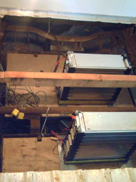 [13th] I got the second
battery installed. Also the 7 to 1 planetary gearset for the Sprint
car's variable torque converter arrived at the post office. (Nobody
will ship valuable items through the mail and they charge much extra
for courier delivery, but half the time they show up here at the post
office anyway. Then I get the collect bill from Fedex that seems to
include both "brokerage" charges plus the cost of mailing it.)
[13th] I got the second
battery installed. Also the 7 to 1 planetary gearset for the Sprint
car's variable torque converter arrived at the post office. (Nobody
will ship valuable items through the mail and they charge much extra
for courier delivery, but half the time they show up here at the post
office anyway. Then I get the collect bill from Fedex that seems to
include both "brokerage" charges plus the cost of mailing it.)
[14th] I wired up the batteries. In between
the two stacks, the "36V" point, I mounted a fuse holder for a 400 amp
fuse. Then a wire to connect the "+" of the front stack to the fuse
holder, and another from the other side of the fuse holder to the "-"
of the rear stack. I cut off the connector terminal from the "+" wire,
the "72V" point, and crimped on one with a larger hole for the 1/2 inch
battery bolt. The cable was just about the right length.
At the "-" or "0V" wire, it finally dawned on me that I
should put in a shunt for a voltage-current meter, just as I had just
done in the Sprint. I couldn't use the TK15 type coulometer that I had
used in the Sprint. Those were rated 80 volts max. The "72 volt" truck
could charge to up to 84 volts. So I used a dual LED display
voltage-current meter I had bought earlier (200V max), that had a 200
amp shunt. (bought so long ago I looked through the whole electronics
lab before I found it.) I think I can estimate how high or low the
battery is pretty well by the voltage. If it's over 79 that's pretty
charged (although at 20°C, 84V would be 100%). If it's 70V it's
getting down there and if it's hitting below 66V while underway it's
overdue for a charge.
(In fact I had a choice of 100, 200 or 500 amp shunts as I
had bought three of these units. If the truck's Curtis AC35, 72 volt
motor is indeed 10KW, then 10000W/72V=139 amps max.) I made a plywood
mounting piece to hold the shunt. (The negative cable had a couple of
inches to spare by going to the shunt instead of direct to the battery
terminal - I hadn't needed to change it. Sigh!)
At the end of the day it was all together but it was
getting late I and didn't put the fuse in. Also I hadn't mounted or
wired in the meter, so nothing was connected to measure using the
shunt. (Do I do that next, or press on with the torque converter?)
[15th] When I had a few months ago (at long last) measured the
current with the
ignition off and discovered the the batteries were being continually
depleted instead of sitting idle, I had thought it must be the truck's
(unplugged) 72 volt battery charger drawing current. But having removed
it, when I connected the new batteries, I found something was still
drawing the same tens of milliamps continually from them! It turned out
that the charger for the 12 volt battery is "on" even if the ignition
is "off", holding the 12 volt battery under the seat at 13.4 volts by
drawing from the main batteries!!! This fine little feature from the
manufacturer has destroyed around 3000$ worth of my batteries by
totally discharging them over time when I left the truck sitting
unused. (If anything was to be lost I would much rather it was just the
one small 12V battery - and even that one would probably last better if
left idle than under continuous charge! Again, small wonder Miles went
out of business!) Now, where is said charger so I can rewire it
properly through the ignition switch?
When I connected the fuse, the motor wouldn't turn.
There's an interlock sensor switch on the brake fluid and it won't
start unless you're pressing the brake pedal. The main reservoir was
empty. No brakes. Again. Hmmpf! I had already replaced the brake line
to the left rear wheel 2 or 3 years ago when it was running. Where else
was it leaking out over the months? I refilled the cylinder. The pedal
still went to the floor. Past experience says it eventually refills the
lines by itself and the brakes and truck (motor) should start working.
I had lots of brake fluid and could worry about it later. In the
meantime it might take a day or two for the fluid to percolate down.
I routed a wire from the batteries and shunt up onto the
dash, via some holes, under some trim, and by drilling a small hole in
the dash next to the speaker. (Wait, speaker? The truck has no stereo!)
Then I figured I might as well make a small panel to mount on top of
the dash for both the voltage-current meter and the bicycle speedometer
(the truck's original speedometer having no transmission to plug into
any more). There seems to be some "scope creep" going on in this
variable torque converter experiment! Oh well, it all needs to be done.
[16th] I located the DC to DC converter that charged the 12 volt
battery, under the passenger's seat. It plugged in with a 5 wire plug,
so I simply unplugged it. One problem solved. One wire was labeled
"enable". WHY in God's name would they enable it with the ignition
OFF?!?
I connected the 72 volts through the multimeter on "amps"
across the fuse holder. No current after the initial pulse (which
occurs to charge the capacitors in the motor controller). The way it
should always have been but wasn't. I left the DC to DC unit unplugged
and fastened the fuse for the 72 volt main power into place, reassured
that the batteries wouldn't be bled to death if I left it that way.
Then I checked the voltage with the test leed still in the
"10 amps" socket. ZAP! A new fuse for the blown one didn't fix it. On
October 3rd it was either throw out my fine Fluke multimeter or fix it.
I thought maybe a chip in the meter was fried. But I tried to short out
a power supply across the meter on amps, and nothing happened. That
said there was no connection. With a magnifying glass I found a tiny
broken trace on the circuit board from the "-" test leed. I bridged it
with a thin wire and
solder, and the meter lives on! (YAY!)
The brakes still hit the floor so I couldn't try the motor
yet. (Might I actually have to bleed them? But the level in the
reservoir had dropped a bit.)
I decided the "project creep" was getting out of hand, and
to wait until later to wire in the Volt-Amp meter, the speedometer,
reroute the 12V charger's "enable" and the 72V battery charger. (two @
36V... Actually I got four 40 volt, 10 amp power supplies in case I
want to charge at 20 amps instead of 10.) All the batteries should have
plenty of energy for initial tests of the torque converter, and there
should be some "feel" for how hard the motor was working even
without an ampmeter. And of course the truck should move - easily and
smoothly on the concrete floor, then with more challenge on the rough
lawn and hills.
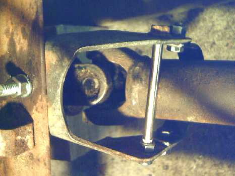 I put the
assembled shaft in and held it propped up with a block of wood. For a
first test it just needed something to hold the rear end and the drive
shaft up - but something that still would allow it all to turn. I had
an old piece from the truck that had held the original transmission. I
ended up using just a bracket from that, and a long bolt and a piece of
1/8 x 1 steel strap 6 inches long, bent into a "U". This sufficed to
form a circle around the rear driveshaft and hold it at about the right
height. Unless the final housing has something else to replace it, I
plan to also leave this assembly in place just in case so that if the
rear driveshaft - which will now have only a very short overlap with
the planetary's shaft - should ever become disconnected, the front of
it can't drop to the ground and act as a pole vault to flip up the
whole rear of the moving truck.
I put the
assembled shaft in and held it propped up with a block of wood. For a
first test it just needed something to hold the rear end and the drive
shaft up - but something that still would allow it all to turn. I had
an old piece from the truck that had held the original transmission. I
ended up using just a bracket from that, and a long bolt and a piece of
1/8 x 1 steel strap 6 inches long, bent into a "U". This sufficed to
form a circle around the rear driveshaft and hold it at about the right
height. Unless the final housing has something else to replace it, I
plan to also leave this assembly in place just in case so that if the
rear driveshaft - which will now have only a very short overlap with
the planetary's shaft - should ever become disconnected, the front of
it can't drop to the ground and act as a pole vault to flip up the
whole rear of the moving truck.
The brake pedal still went
to the floor so I couldn't try to test it. Maybe tomorrow? (How long
was it last time after filling the cylinder before I discovered the
brakes were magicly working again? I wasn't using the truck - Can't
remember. Hmm, could it have been a week or two rather than a day or
two?)
[19th] Finally the brakes were grabbing enough that if I pumped them a
bit the motor turned. But the truck didn't move. It didn't even feel
from inside like it was trying, even on the level cement of the garage
where I could push it easily enough by hand. And instead of being
silent as
expected, there was a pretty loud noise. A video set up on the floor
beside the truck showed that the motor turned one way and the planetary
gear housing turned the other (1/4 as fast we presume). including when
I revved it up a bit. Not enough magnetic interaction, I presumed. But
the noise was pretty loud.
I decided to try again. This time I went forward (into
less space) instead of backward, and I revved it up harder, briefly.
The truck lurched forward a bit. In the video one could see the drive
shaft twist. Then for some reason it (both shaft and truck) went back
to where it was. It seemed to me the join between the planetary gear
output and the rear drive shaft seemed to be slipping. It was a weak
point, sort of hacked together, and there were a couple of set screws I
hadn't bothered to do up. The key slipping against the inside splined
shaft might explain both the noises and the reluctance to move, and why
it might only move forward.
I tightened the set screws, but the result was the same.
I'm still puzzled why the truck would only move a bit, and then go back
to where it started. I could push it easily enough, and it didn't do
that. And what was the noise? It certainly didn't sound good.
I tried a fourth time, in reverse again and with revving
higher. This time (probably just with the higher revs) the drive shaft
twisted a bit. and then went back as I stopped. Again I could still
push it quite easily.
I tentatively concluded:
(1) that there was just enough magnetic interaction to budge the truck
on the level cement, at least if well revved up.
(2) that it wasn't nearly as much as needed.
(3) that the drive shaft might be jamming on the bolt heads in the loop
I made to contain it as soon as it starts to turn. Of course it needs a
proper bearing to hold the front centered and freely spinning. That
might explain why the truck would start to move but then stop again,
but looking at the videos I'm not at all sure.
(4) that the drive shaft turns back again owing to inertial forces as
the disks and planetary gear spins decelerate when I stop pressing on
the pedal.
(5) In one video I saw some pretty serious vibration up at the motor
end of the shaft. It probably explains the noise, and says that the
housing for the whole unit is a must soon rather than later. (This is
probably the vibration I thought was caused by an unbalanced shaft when
I first made it just before the batteries were all murdered by the
truck.)
As far as magnetic interaction, changing the rotor to a
Halbach configuration should produce a good increase. When I started I
had mistakenly thought that the ring gear would have low torque acting
on it, like the sun gear driving it. In fact, in a 5 to 1 gearset, the
speed reduction and torque on the body/ring is 5 - 1 = 4 times the
input torque, at 1/4 speed. So a lot more magnetic interaction is
required than I had at first assumed. It can be done.
Looking again at the videos, I couldn't really see the gap
between the two rotors. Inspection revealed that that was because the
alume rotor on the motor shaft had come loose. It was both touching the
magnet rotor (making all that noise) and not always turning with the
motor shaft. That explained a lot of things. Too bad about the shaft
being undersize and there being only one setscrew to hold the rotor in
place. All other conclusions needed to be placed on hold until I could
get it to stay in place long enough to test again. After that they were
thrown out the window.
It Works!
Late in the evening I went into the garage and managed to
get an allen wrench in and tighten the rotor hub without disassembling
the whole thing. I tried again. GREAT ZOT!, it moved!
and without all the noise, which obviously would have been the rattling
and vibration of the loose disk. With the motor at "idle" speed the
planetary's body just turned backward, but with a little push on the
"electron pedal" the truck pulled forward. or backward. Perhaps the
magnetic-mechanical balance isn't bad after all.
Observing the video, the planetary body was still turning
backward as the truck moved. So the effective reduction ratio was
greater than 5 to 1. Pushing my luck, I wondered if the truck would
crawl over a 1 by 4 board. I found a small piece of 3/4 inch plywood
and a short 2 by 4 with rounded corners and put them in front of the
left front wheel. It went up the plywood fine, and then already moving
skipped over the board. Backing up it didn't want to go back over the
board without a run at it. Just revving it up a bit didn't get it over.
This time once or twice the truck started moving a bit with the motor
at "idle" speed, not pressing the pedal. And at one point, I observed
(in the video) the body of the planetary slowing down as I backed up
instead of staying about the same or speeding up - a lower gear ratio
when there was lower torque.
The mechanics being rather kludjed I didn't want to push
the pedal too hard, rev very high or test for very long. It all needs
to be redone properly now with the rear bearing and a solid housing. I
still worry about the short and mismatched overlap connection between
the gearset output and the rear drive shaft. That little bit carries
the most torque. But it works!
The fact that it wouldn't go over the 2 by 4 without a run
(or more "oompf" from the pedal than I wanted to give it) probably says
the magnetic coupling, tho it works, is still rather too light.
Unfortunately it wasn't in the video. With the truck moving now and the
camera not following I missed being able to review the actions of the
mechanism for most of this run. I should probably make a mounting on
the side of the truck to hold the camera pointing at the mechanism and
move along with it. It should be great to see the planetary's body stop
turning backward and start going forward as the truck gains speed.
(I'll also have to put a transparent side or removable cover on the
housing so the workings can be seen.)
I didn't think to check the alume rotor right after to see
if it was getting warm. I trust the tests weren't long enough to heat
it significantly.
[20th] I contrived a way to mount the video camera upside down on the
side of the truck with a small piece of plywood, two C-clamps, and an
odd bolt I had noticed earlier with one end "lag bolt" threads and the
other end 1/4"-20 TPI: camera tripod threads. I opened the garage door
and backed the truck out of the garage, accelerating a bit into the
uphill slope on the lawn. I stopped (the mechanism didn't come to a
total stop) and was gratified that the truck would still start moving
again easily with the back wheels going up the shallow slope on the
lawn. (I only went about 16 feet, concerned about potentially damaging
the "ckludjy" mechanism or having something come loose.) Then I drove
forward back into the garage.
The video showed the body of the planetary spinning,
slowing and reversing direction both ways as the speed and load changed
- exactly as intended.
The alume disk got warm even in that short time, maybe 110
or 120°F (40-50°C). I have no idea how much energy that heat
represents compared to the total energy that was used in moving the
truck. Probably a few percent? 10% or more? But again I think that more
magnetic coupling rather than less is the solution. In spite of more
potential for electromagnetic heat with "X" motion, the magnet rotor
and alume disk ideally wouldn't get moving so fast relative to each
other, which I would think should substantially reduce heat. (And if
needed, maybe some heatsink fins on the back or outside of the disk
would help dispell any heat that was generated. That would probably be
for a production model.)
[21st] I got my video clips together, made a few more short snips of
explanations, spliced and edited everything together, and uploaded a 21
minute video about the torque converter to youtube.
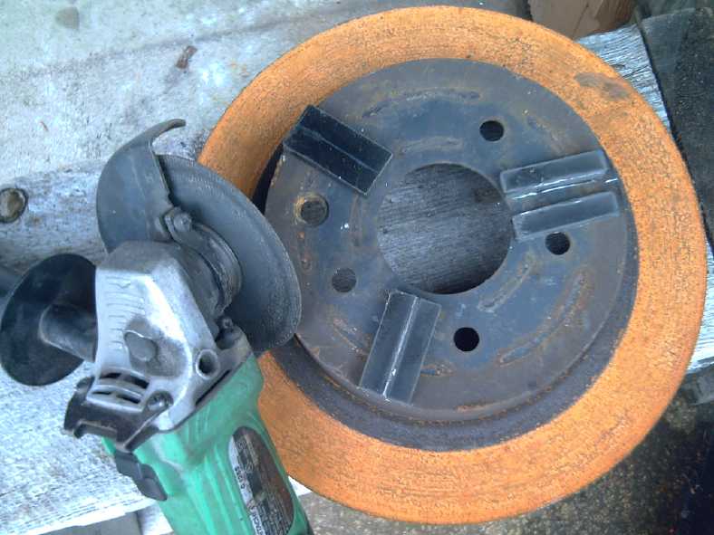 [23rd] For more magnetism I
started by splitting three new magnets (2" x 1" x .375") down the
middle to mount on their sides for the Halbach configuration effect.
The .375" size, now the width, should fit between magnets already on
the rotor. That should magnify the magnetic fields by 1.5 to 2 times.
[23rd] For more magnetism I
started by splitting three new magnets (2" x 1" x .375") down the
middle to mount on their sides for the Halbach configuration effect.
The .375" size, now the width, should fit between magnets already on
the rotor. That should magnify the magnetic fields by 1.5 to 2 times.
I made one pass at a time and then let them cool so as to
not heat them up and cause them to lose magnetism. It was tedious. (The
dust, with the reactive neodymium, still burned, glowing red - some of
it stuck to the magnet. I touched some after it stopped glowing to wipe
it off and burned my thumb.). After the first magnet I realized that if
there were several to do, I could go from one to the next to the next
so the first one would be cool again by the time I got back to it. I
simply stuck the magnets onto a thick steel chunk (brake rotor disk)
and their own magnetism held them securely.
The other thing that could help with flux would be a
thicker alume disk. That might improve things by maybe 1.5 times as
well. (19mm / 3/4 inch thick alume?) Also the alume you buy is usually
an alloy. Pure alume would be better. (Soft drink cans are pure alume
because it forms best from a 'chunk' int a can shape. But I need a
forge to melt them into a rotor!)
And the 12 magnet motor rotor I used has only 6 poles, the
polarity of the magnets being
N N S S N N S S N N S S . I could probably make a more optimized
Halbach rotor with 12 poles that would also have more flux.
Double what it has now would probably be notably better,
considering the trouble it had climbing over the 2 by 4. Triple or
quadruple should be excellent - maybe even too much, limiting
acceleration with too low reduction ratios. But somewhere near triple
should be attainable without going to two magnet rotors.
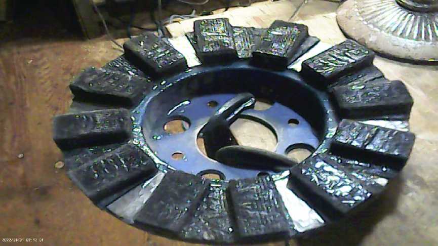 [28th] I
dismounted and disassembled the unit. I used a hacksaw to cut the
epoxied polypropylene strapping/webbing cloth from between the magnets
where magnetic polarity changed in order to have bare rotor to epoxy on
the skinny sideways magnets, 'I':
[28th] I
dismounted and disassembled the unit. I used a hacksaw to cut the
epoxied polypropylene strapping/webbing cloth from between the magnets
where magnetic polarity changed in order to have bare rotor to epoxy on
the skinny sideways magnets, 'I':
SIN NIS SIN NIS SIN NIS. When I got a chisel under the separated pieces
of epoxied PP, they popped off distressingly easily. Wow! The epoxied
cloth had been a continuous ring around the rotor, now it was 6 short
patches, each covering two magnets. How easy would it be for the
magnets to fly off?
I somewhat savagely roughed up the bare spots for the new
magnets with the edge of the zip disk in the angle grinder. I had
already thought to get some fresh epoxy resin from the building supply
that was both newer and probably a better brand/formula than what I
had, but I hadn't put it on my shopping list and forgot to get it.
(Drive back to town again?, sigh!)
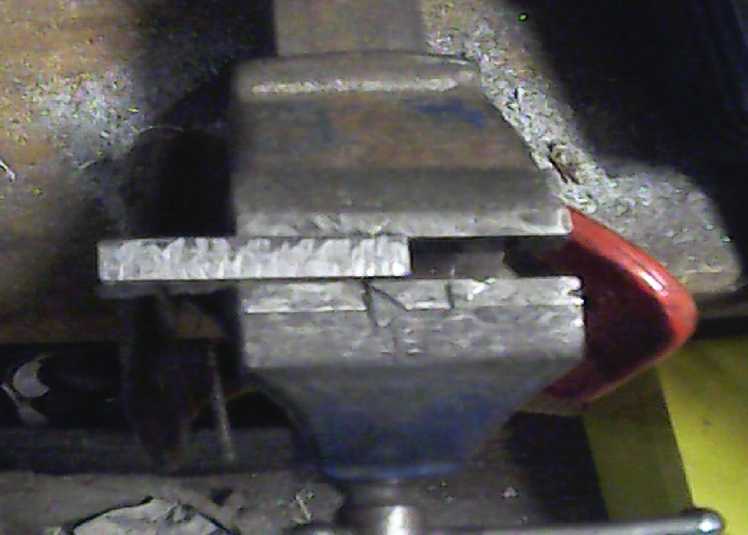 Finally I
ground down the protruding edge on the 6 skinny magnets, formed because
when splitting them in half I had snapped them off before the grinder
was totally through. (Hey, it was tedious cutting, eh? And the deeper
in, the tougher/slower the cutting.) Then I tapped them all over the
'leveled' contact face with the edge of the running zip disk to roughen
it up.
Finally I
ground down the protruding edge on the 6 skinny magnets, formed because
when splitting them in half I had snapped them off before the grinder
was totally through. (Hey, it was tedious cutting, eh? And the deeper
in, the tougher/slower the cutting.) Then I tapped them all over the
'leveled' contact face with the edge of the running zip disk to roughen
it up.
[29th] Bought the epoxy,
the best looking of two choices at the building supply. "System 3 -
G2". "Bonds to wood, metal and concrete. SUPERIOR STRENGTH ON THE
TOUGHEST-TO-BOND WOODS" (180$ for 3 US pints - it had BETTER be really
good stuff!)
I rubbed solvent on each rotor face and the magnet face to
be glued before applying the epoxy, in accordance with the instruction
on the epoxy. And I peeled off any loose plating anywhere on the
magnet. It proved surprisingly easy to epoxy each magnet to the rotor.
Although the magnetic forces were strong, if the magnet was slid in
from the outside, it repelled from the magnets on each side rather than
clamping onto one of them. (If it attracted it was the wrong way
around.) It was attracted to the rotor metal, so as long as it wasn't
lifted up much above the steel it didn't tend to suddenly flip and jump
out. (I tried to lift them a bit to keep from scraping off the epoxy as
I slid them in.) When it was pushed in just past even with the other
magnets, it stopped wanting to pop out to the outside. So it could just
be put into place and it would center itself between the other two
magnets. They didn't need some jig to hold them in place while the
epoxy set.
I didn't mix much epoxy, but I saved the rest and the
brush in the freezer to thicken it up around the new magnets after they
had set in place, and coat the unplated, unprotected faces. Because of
the kerf of the zip disk when cutting, the new magnets didn't stick up
quite as high as the others and so were slightly recessed. I don't
think that's a problem - in fact, given that the cuts weren't all
exactly 90° so they didn't all sit quite square, it's probably an
advantage.
The 6 skinny magnets were cut from 3 full size. That means
15 magnets equivalent instead of 12 is 25% more magnets as well as
Halbaching it, so there's a good chance it'll be over 1.5 times and
headed for twice as much field. But as it is its depth of field would
probably be a good match with a 20mm or even one inch thick alume disk
rather than the ~10mm one. It would probably be better if it went
NSNSNSNSNSNS rather than NNSSNNSSNNSS. It would be a shallower
field but with more field transitions. Then if it had a skinny magnet
between each of the others - 12 half magnets on their sides between 12
full ones (NISINISINISINISINISINISI), which would obviously still fit
on a 10 inch rotor - it would be 18 magnets equivalent, more ideally
"Halbached", and surely have an awesome field strength. Anyway I'm
using up these old rotors for this torque converter unless poor
performance forces me to do such an "ultimate" one. (or a thicker alume
disk, or both. I don't think a costly, heavy copper disk is called for.
It would cost more than any rare earth magnets it saved.)
[30th] I used up the epoxy touching up and coating the new magnets. It
finally occurred to me why the rear driveshaft was splined and
originally free to slide in and out: when the truck hit bumps, the rear
suspension would move and that join was where the drive mechanism had
some slack if it moved back and forward a bit.
[Oct. 2nd] I cut the motor shaft a little shorter to make room for the
bearing at the back. I ended up cutting twice (oops, too far!), moving
the alume rotor 2 or 3 times, and finally I put it back together with
almost no magnet gap - a couple of mm. With the 'Halbached' rotor there
was a lot of resistance to turning it, or the same resistance at
considerably lower speeds than before.
It fit on the truck with a couple of mm to spare on the
shaft length. I decided to try a tiny test drive, but as I hadn't put
the shaft key back on for this test fit, it had only 2 little set
screws holding the rear drive shaft. After tightening them twice (and
worrying that the threads might strip), I got it to move. At "idle
speed" the truck wouldn't move ahead, but a small press on the pedal
got it to go. In reverse it started moving at "idle speed" and I didn't
press on the pedal. Then the drive shaft started slipping again.
The new video showed that the body of the planetary turned
much more slowly. In reverse once the truck started moving, it almost
stopped. So I expect the magnetic coupling is now about right.
In fitting the mechanism and doing these tests, the amount
of wobble I was seeing with the whole unattached gearset assembly and
long shafts bothered me, and it occurred to me I should put a steady
bearing on the long shaft from the motor, at the rotors end, in
addition to the one at the back end of the planetary. I'll feel much
better
about the stability and high speed operation.
It's going to be great!
Charts
I did spreadsheets with some
hypothetical values. I found it had to be a three dimensional
spreadsheet: Torque
versus gear ratio and other parameters, and Speed versus gear ratio and
parameters. That being difficult, I did four two-dimensional
spreadsheets: Torque =
0, 'x1', 'x4' and 'x8' for 'coasting', 'cruising', 'accelerating' and
'pedal to the metal' resulting in an 'educated guess' of 0, 50, 200 and
400 RPM slip
between the alume disk and the magnet rotor. (and later, 'x16'.) These
can't be taken as
being anything like literal figures because they're going to change for
each torque converter and with the strength of the magnetic coupling
compared with all the mechanical factors. However, the "x1" and "x4"
graphs may not be so far off for the truck for power in watts, since
the maximum power
reads "9400" (arbitrary units) and the truck's motor is 10000 watts.
But the "x8" 'pedal to the metal' graph could also be
closer at lower power
levels if there's less magnetic
coupling, and then 'x16' would be for higher acceleration while 'x1'
would be almost coasting. Which ones are most realistic for the truck
under what loads is to be determined.
I've rounded off the efficiencies to whole percents. How
to calculate them got convoluted. I think I've calculated them
correctly but I'm not 100% certain. Here is my
reasoning:
1. For a given torque the slip is a fixed RPM, and the power lost is
related to that RPM of slip, at any vehicle speed and overall RPMs.
2. If the slip is (eg) 200 RPM 'lost' from the motor to the body of the
planetary, and the nominal reduction of the gearset is 5 to 1, that
translates out to 40 RPM 'lost' at the output.
3. So the efficiency would be (RPMoutput)/(RPMoutput+40), *100 for
percent.
a. So if the motor was turning 200 RPM, the planetary gear would
be stationary at 0 rpm and the output would be 40 RPM. Eff =
(40)/(40+40), *100 = 50%. (a momentary figure with the
vehicle just starting to move.)
b. Of course the faster everything is turning, the less
significant the 200/'40' RPM slip is in proportion. So at 1000 motor
RPM the body is spinning 800 RPM (still 200 RPM slip) and the output is
going 840 RPM. Thus, (840)/(840+40) * 100 = 95.45% efficiency.
Hopefully this method of calculation is correct, or if
not, at least a fair approximation. I was surprised how high the
percentages turned out to be except at very low speeds. Theoretical
efficiencies at typical driving speeds and
motor powers look quite good - over 95%. Of course, much depends on the
strength of the magnetic coupling and hence the amount of slip for a
given torque.
High magnetic coupling will give the highest efficiencies but the
lowest "gear ratios" at low speeds and hence the lowest acceleration
and hill climbing capacity. Inefficiencies, owing to slip in the
magnetic coupling, will heat the alume disk the most. (That's where the
lost power goes - temperature hasn't been measured yet. It was rather
warm on first tests, but the magnet rotor's magnetic field has now been
"Halbach" strengthened.)
It is of note that much of the change in effective gear
ratios occurs at very low speeds. (After all, going from 1 to 2 KmPH is
a doubling of speed, and 2 to 4 is another doubling.) But it also
varies with strength of acceleration. In the "x8 torque" case the ratio
is still over 2 to 1 up to 15 KmPH.
It should also be noted that the ZX40 test vehicle has a
2.2 to 1 additonal gear reduction in the rear differential, so overall
it drops from a nominal 11 to 1 toward 2.2 to 1 (rather than from 5 to
1 toward 1 to 1). 2 to 1 in the torque converter is 4.4 to 1
from the motor to the wheels. (There is nothing that seems practical to
eliminate whatever the inefficiency is of the rear differential in the
test vehicle. Also the additional 2.2 to 1 makes it a better match for
the vehicle's Curtis AC35 motor RPMs. But if I do one for the Sprint
car with
the 0-2000 RPM forklift motor or an axial flux BLDC motor (also high
torque, low RPM), the torque converter will go direct to the CV drive
shaft on a wheel.)
Case torque = 0: No torque required. ('Coasting')
Truck
Speed
(KmPH)
|
Drive Shaft
RPM
|
Gear Body
RPM
|
Motor RPM
|
Gear Ratio
(n:1)
|
0
|
0
|
0
|
0
|
(5.0)
|
5
|
110
|
110
|
110
|
1
|
10
|
220
|
220
|
220
|
1
|
20
|
440
|
440
|
440
|
1
|
30
|
660
|
660
|
660
|
1
|
et
|
cetera
|
|
|
|
Case torque = "x1", magnetic slip = 50 RPM @ motor shaft ('Cruising')
Truck
Speed
(KmPH)
|
Drive Shaft
RPM |
Gear Body
RPM |
Motor RPM |
Gear Ratio
(n:1) |
Mot.Power
(arbitrary
units)
|
Efficiency
(%)
|
0
|
0
|
-12.5
|
37.5
|
(5.0)
|
37.5
|
-
|
5
|
110
|
97.5
|
147.5
|
1.34
|
147.5
|
90
|
10
|
220
|
207.5
|
257.5
|
1.17
|
257.5
|
95
|
20
|
440
|
427.5
|
477.5
|
1.09
|
477.5
|
97
|
30
|
660
|
647.5
|
697.5
|
1.06
|
697.5
|
98
|
40
|
880
|
867.5
|
917.5
|
1.04
|
917.5
|
99
|
50
|
1110
|
1087.5
|
1137.5
|
1.03
|
1137.5
|
99
|
60
|
1320
|
1307.5
|
1357.5
|
1.03
|
1357.5
|
99
|
70
|
1540
|
1527.5
|
1577.5
|
1.02
|
1577.5
|
99
|
80
|
1760
|
1747.5
|
1797.5
|
1.02
|
1797.5
|
99
|
100
|
2200
|
2187.5
|
2237.5
|
1.02
|
2237.5
|
99
|
Case torque = "x4", magnetic slip = 200 RPM @ motor shaft
('Accelerating')
Truck
Speed
(KmPH)
|
Drive Shaft
RPM |
Gear Body
RPM |
Motor RPM |
Gear Ratio
(n:1) |
Mot.Power
(arbitrary
units)
|
Efficiency
(%)
|
0
|
0
|
-50
|
150
|
(5.0)
|
600
|
-
|
5
|
110
|
60
|
260
|
2.36
|
1040
|
73
|
10
|
220
|
170
|
370
|
1.68
|
1480
|
85
|
20
|
440
|
390
|
590
|
1.34
|
2360
|
92
|
30
|
660
|
610
|
810
|
1.23
|
3240
|
94
|
40
|
880
|
830
|
1030
|
1.17
|
4120
|
96
|
50
|
1110
|
1050
|
1250
|
1.14
|
5000
|
96
|
60
|
1320
|
1270
|
1470
|
1.11
|
5880
|
97
|
70
|
1540
|
1490
|
1690
|
1.10
|
6760
|
97
|
80
|
1760
|
1710
|
1910
|
1.09
|
7640
|
98
|
100
|
2200
|
2150
|
2350
|
1.07
|
9400
|
98
|
Case torque = "x8", magnetic slip = 400 RPM @ motor shaft ('Pedal to
the metal')
Truck
Speed
(KmPH)
|
Drive Shaft
RPM |
Gear Body
RPM |
Motor RPM |
Gear Ratio
(n:1) |
Mot.Power
(Arbitrary
units)
|
Efficiency
(%)
|
0
|
0
|
-100
|
300
|
(5.0)
|
2400
|
-
|
5
|
110
|
10
|
410
|
3.73
|
3280
|
58
|
10
|
220
|
120
|
520
|
2.36
|
4160
|
73
|
20
|
440
|
340
|
740
|
1.68
|
5920
|
85
|
30
|
660
|
560
|
960
|
1.45
|
7680
|
89
|
40
|
880
|
780
|
1180
|
1.34
|
9440
|
92
|
50
|
1110
|
1000
|
1400
|
1.27
|
11200
|
93
|
60
|
1320
|
1220
|
1620
|
1.23
|
12960
|
94
|
70
|
1540
|
1440
|
1840
|
1.19
|
14720
|
95
|
80
|
1760
|
1660
|
2060
|
1.17
|
16480
|
96
|
100
|
2200
|
2100
|
2500
|
1.14
|
20000
|
96
|
The figures, while arbitrary, seem indicative of probable
performance. Testing is still
in the earliest stages and it may prove that 'x8' sorts of reduction
ratios and efficiencies will apply at lower accelerations or even at
cruising power levels and that there might be an 'x16' for strong
acceleration. The 'x1' and 'x4' graphs may indicate too much magnetic
coupling resulting in too low effective gear ratios at low speeds and
during acceleration. But even the 'x8' efficiencies are substantially
better than the
"80+%" efficiencies of today's automatic vehicle transmissions, and
much
better than older "70% efficient" stick shifts and "60%" automatic
transmissions.
In fact, let's look at the 'x16' case, too:
Case torque = "x16", magnetic slip = 800 RPM @ motor shaft (Strong
acceleration with lower magnetic coupling)
Truck
Speed
(KmPH)
|
Drive Shaft
RPM |
Gear Body
RPM |
Motor RPM |
Gear Ratio
(n:1) |
Mot.Power
(Arbitrary
units)
|
Efficiency
(%)
|
0
|
0
|
-200
|
600
|
> (5.0)
|
9600
|
-
|
5
|
110
|
-90
|
710
|
6.45
|
11360
|
41
|
10
|
220
|
20
|
820
|
3.73
|
13120
|
58
|
20
|
440
|
240
|
1040
|
2.36
|
16640
|
73
|
30
|
660
|
460
|
1260
|
1.91
|
20160
|
80
|
40
|
880
|
680
|
1480
|
1.68
|
23680
|
85
|
50
|
1110
|
900
|
1700
|
1.55
|
27200
|
87
|
60
|
1320
|
1120
|
1920
|
1.45
|
30720
|
89
|
70
|
1540
|
1340
|
2140
|
1.39
|
34240
|
91
|
80
|
1760
|
1560
|
2360
|
1.34
|
37760
|
92
|
100
|
2200
|
2000
|
2800
|
1.27
|
44800
|
93
|
Here the mechanism attains higher effective reduction
ratios than the design of the planetary gearbox at lowest speeds and
(we presume) under strong acceleration as the body of the planetary
turns
backward. And still, passing through the speed of 50 KmPH as power
increases the efficiency hits 87% and it will rise as acceleration is
reduced. All of these are excellent figures, seemingly well over 90%
for most
any typical road trip.
Sprint
Car:
Tires, TK15 (TK15H) Coulometer
[6th] I was worried about being able to find new tires for the Sprint.
I was about to ask the garage if they can order its 12 inch tires. But
first I finally I looked in my storage at two used tires that size that
I had got 8 or 9 years ago ("good condition, free for pickup"
advertised
on UsedVictoria.com). I figured they were as old and wouldn't be much
better than the ones on the car, but in fact they look newer and
better. The rims look rather rusty, but the tires look pretty new - no
cracks in the sidewalls, good if not full tread and they're still
inflated after all this time. "Firestone Gas Saver" - sounds
good to me! I'll put them on
the front wheels. A rear tire blowing is generally not catastrophic and
I'll have two full size spares in case one does. Good enough for a few
years. (I'm
now assuming the variable torque converter will finally get it
on the road
sometime in the foreseeable future!)
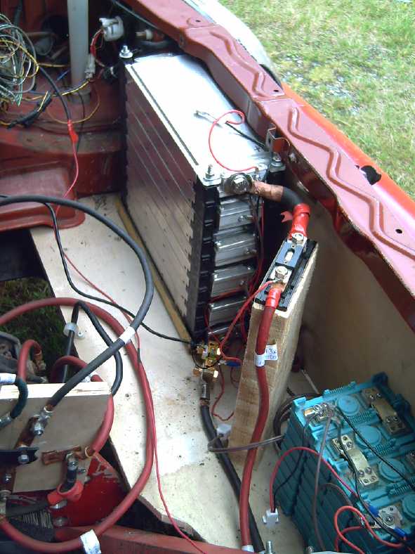 [7th]
In connection with doing the torque converter in the truck I had to
take one of the batteries from the Sprint. The truck needs two of my
three 36 volt stacks to get its 72 volts.
[7th]
In connection with doing the torque converter in the truck I had to
take one of the batteries from the Sprint. The truck needs two of my
three 36 volt stacks to get its 72 volts.
According to my rough calculations and expectations
[and assuming it will have the variable torque converter] I should
still be
able to drive it to town and back (55 Km) even with just one battery
stack
instead of two (36 V, 120 AH = 4320 WH - should use well under 4000 for
that trip).
(If instead I could put all three stacks in the Sprint for 13KWH, it
should probably be able to make it to the farthest town on the island,
Masset, and back. 170 Km total.
The Nissan Leaf can't do that with 24KWH. According to its
"Km/KWH" reading, it takes
around 7 to 9 KWH to drive to town and back. 7 is in summer sun; 9 is
wet road or cool to cold weather. I've never driven it more than about
110 Km, in summer, with the reserve saying just under 20% and flashing
red. Whatever the Leaf's efficiency it weighs
twice as much and surely has more road/tire resistance with its fat
tires.)
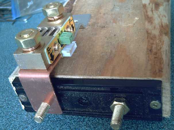 I didn't want to leave the
Sprint with the power disconnected and not working. And I figured while
things were disassembled was the time to install the coulomb meter I
bought some months ago so I could see the state of charge and voltage
of the battery. Of course it had a shunt resistor that had to go in the
battery line. I thought I had a good way to put and connect it on the
block that the main battery fuse was on.
I didn't want to leave the
Sprint with the power disconnected and not working. And I figured while
things were disassembled was the time to install the coulomb meter I
bought some months ago so I could see the state of charge and voltage
of the battery. Of course it had a shunt resistor that had to go in the
battery line. I thought I had a good way to put and connect it on the
block that the main battery fuse was on.
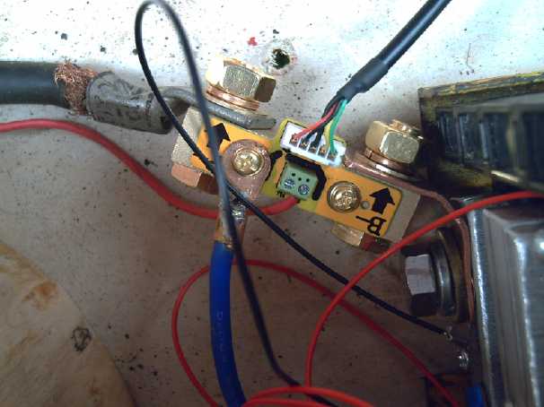 Then it dawned
on me that it said "B-", not "B+". It had to go on the ground side!
Typical, actually. I
managed to use the same copper plate strap. By the end of the day I had
the battery and balance charger reconnected and the TK15 - 350 amp
coulometer wired and working, but not mounted on the dash. The 2 meter
long optional cable I got with it was just long enough. The TK15
seems to come in a variety of voltage current ratings and may(?) have
more than one manufacturer.
Then it dawned
on me that it said "B-", not "B+". It had to go on the ground side!
Typical, actually. I
managed to use the same copper plate strap. By the end of the day I had
the battery and balance charger reconnected and the TK15 - 350 amp
coulometer wired and working, but not mounted on the dash. The 2 meter
long optional cable I got with it was just long enough. The TK15
seems to come in a variety of voltage current ratings and may(?) have
more than one manufacturer.
There was no manual and I watched a video on youtube
showing how to use it. I set it to 40V fully charged and 33
discharged, 120 amp-hours. It seems like a good unit. In addition to
what my other battery monitors do, it tracks the current in and out and
estimates the state of charge of the battery, expressed in percent and
amp-hours remaining. The backlight pulses on and off while it's
charging, even a little bit. It stays on while a load is on and goes
out if nothing at all is happening, to avoid itself discharging the
idle battery. I told it the battery was at 100%.
The current readings to the motor while driving looked
reasonable.
Then I took a test drive - the usual, across the acreage
and back. Everything seemed to work fine and stayed cold except my
crappy flattened copper waterpipes forward-reverse switch got warm, as
usual. If I picked the meter up off the floor and held it so I could
see
the amps and volts. It showed 98% charge remaining. It had rained
earlier, and the drive wheel's tire spun on the wet grass much more
easily than it had when the ground was dry.
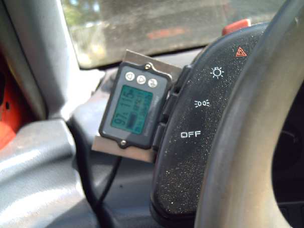 [8th] I mounted the
coulometer on the side of the dash with a couple of "L" bits of
stainless steel. That seemed to be the only place where I could see it
without it being hidden behind the steering wheel or looking way down.
I had a car accident in 1993 (Saved by the seatbelt! An airbag as well
would have saved much trauma.) while looking down for an intermittent
windshield wiper adjustment mounted down at the bottom of the dash, so
I wasnt keen on having my attention diverted far from the road -
probably repeatedly as I check current and charge level readings in my
experimental car.
[8th] I mounted the
coulometer on the side of the dash with a couple of "L" bits of
stainless steel. That seemed to be the only place where I could see it
without it being hidden behind the steering wheel or looking way down.
I had a car accident in 1993 (Saved by the seatbelt! An airbag as well
would have saved much trauma.) while looking down for an intermittent
windshield wiper adjustment mounted down at the bottom of the dash, so
I wasnt keen on having my attention diverted far from the road -
probably repeatedly as I check current and charge level readings in my
experimental car.
For the same reason I have one chief complaint with the unit:
the display is too small. Instead of taking a quick glance one must
peer at it to locate the desired figure. This again can distract
attention
from the road for an undesirably long period.
It would be great in a stationary application, but it's
not ideal for a car or electric bicycle (which seems to be one chief
application.)
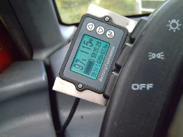 (This picture shows the
coulometer better but less as the driver sees it.)
(This picture shows the
coulometer better but less as the driver sees it.)
[9th] When recharging I noticed that the
TK15 said 4.18 amps, but the wall monitor said 1.93 amps and the solar
charge controller (which I know reads somewhat high) said 2.1 amps. So
it was reading, like, over double. Something is definitely askew here!
I started wondering if I wasn't supplied a 350A coulometer with a 100A
shunt? or something.
I got out the clamp-on ampmeter and took another test
drive
with it on the "B+" wire to the motor controller in the cab. It's hard
to tell exactly with the current bouncing around between 30 and 115
amps and not being able to read both at once, but on average it and the
TK15 seemed to agree quite well. I guess it's just at low currents unit
gets confused... or only during charging. Well, 2 amps is less than 1%
of its 350 amp range. (Yet is says "0.000 amps" just fine when
everything is off!) But the solar charging (especially late in the
afternoon... or in clouds... or in winter) is going to be at low
currents. The moral of the story: don't trust it when it says the
battery is full - go by the voltage. Discharging at pretty high
currents is likely to be pretty close.
Some days later I noticed that at night, connected to the
PowMr charge controller with the Sprint's battery powering the house DC
system (no more spare batteries!), the backlight stayed on because the
PowMr drew a substantial amount of current (100mA; 4W). With most
battery chargers that could be a "slow death" battery killer (and it
seems every RV I run across the batteries have died over the winter or
whenever and the owner is puzzled and looking for help), but in the
case of the solar charge controller, the charge gets replenished every
morning.
Thoughts: Unipolar "Electric Hubcap" Motor With Halbach Magnet
Configuration
[12th] I ran across Halbach magnet "arrays" or configurations which
magnify their flux by putting it out mostly on one side. I noted this
above in the planetary gearset/magnetic disks toruqe converter above.
All else being equal, increasing the magnetism of the rotor would
increase the motor torque for the same "n" coil current. It might be as
good as the "permanent magnet assist" coil idea proposed a few years
ago in some previous issues, and for which I purchased cylindrical
magnets to go inside the toroidal motor coil cores.
I started thinking about what the unipolar motor would
look like with that. First, as I don't have any 1/2 x 1 x 2 inch
magnets magnetized through the width instead of the thickness, I would
have to cut magnets down the middle with the angle grinder to get a 1/2
x 1/2 x 2 inch shape. These could be turned on their side and
used either individually (every second magnet thin) or (as they would
attract) stacked sideways in pairs, so it would look about the same as
with whole magnets.
Or I could use the 3/8 x 1 x 2 magnets. Cutting with the
angle grinder will take out a kerf anyway so the sideways magnets
wouldn't be quite 1/2 inch tall, so it might work out just about as
well. (Good thing axial flux PM motor use such a wide flux gap that
nothing will hit!)
Well, I used these thoughts and converted the torque
converter rotor to Halbach with 3/8" thick magnets sliced down the
middles. And it is indeed markedly better!
The fact that I don't remember seeing any of these, the
most popular of all magnet shapes, available magnetized through the
width means people haven't been using Halbach configurations with their
axial flux motor and generator designs. I guess everybody else has been
as clueless about them as me.
I could use 1/4 inch thick steel for the rotor - maybe
even 5mm(?) flattened sides from the propane tanks I scrounged. Or even
1/8th inch? Being
that thin I could cut them with a jigsaw and metal cutting blade...
ugg!... or maybe just rough them out with the angle grinder and a zip
disk, then a grinder. Then turn them true on somebody's larger lathe
than mine. I looked at TE News
#163: I had figured on the new motor's rotor to be
330mm, a little over 13 inches. This was the minimum diameter to
readily fit the coils on the stator, so I couldn't reduce the rotor
with the thin magnets idea. If I did use it the "narrow" magnet idea
would "save" 4 magnets (and 4 cuts!), 12 instead of 16 for the 8 magnet
poles, but surely the flux would also be that much weaker. 12 magnets
is what I have on my 10 inch rotors - 13 would be a bigger rotor with
them more spread out, somewhat negating the benefits of the Halbach
configuration. (In TE News #134
I show 8 magnet poles. As I had been
making rotors, there would have been 16 magnets - 2 magnets for each
pole. With the Halbach there would be one plus a sideways magnet
between each pole magnet, so still 16 magnets, with the sideways 8
either "narrow" or "wide".) Unless 16 magnets with 8 skinny ones
between will fit on the 13 inch rotor. I'll have to draw that out and
see what it would look like.
Other "Green" & Electric Equipment Projects
Gardening
 Some Fall Harvesting
[3rd] I picked the red
cabbage in the main garden. Seeds planted in
trays, transplanted out and defended by slug bait, then neglected for
the summer except for general watering. Solid. Dense. WOW! It weighed
2.94 Kg - Just the good head after stripping away outer leaves! This is
by far the biggest cabbage I've ever grown.
 The volunteer green cabbage in the greenhouse made a good,
big solid head, too. These last well in the fridge, but perhaps I
should look into something for late winter - sauerkraut?
The volunteer green cabbage in the greenhouse made a good,
big solid head, too. These last well in the fridge, but perhaps I
should look into something for late winter - sauerkraut?
 Several peppers from the two orange pepper plants I bought
in June (my own seedlings having done so little) started getting ripe.
I started making salads with all vegetables from the garden. Some long
skinny "banana" peppers came along on just one from my own seedlings,
another having been set back when its top broke off. I brought the
pepper plants and some tomatos in pots into the house or the window
greenhouse, along with the coffee bushes. Marina who I got the little
bushes from said one of hers had made a few beans this summer. (Mine
finally got one flower.)
Several peppers from the two orange pepper plants I bought
in June (my own seedlings having done so little) started getting ripe.
I started making salads with all vegetables from the garden. Some long
skinny "banana" peppers came along on just one from my own seedlings,
another having been set back when its top broke off. I brought the
pepper plants and some tomatos in pots into the house or the window
greenhouse, along with the coffee bushes. Marina who I got the little
bushes from said one of hers had made a few beans this summer. (Mine
finally got one flower.)
Some spinach in a long rectangular pot is seen behind. It
kept growing and I occasionally had some, but it gradually became too
bitter so I gave it to the chickens.
The blueberries just kept
on ripening for a couple of weeks but tapered off in the last two, and
in fact I picked the last few berries on the 30th. Occasionally I would
notice that a couple of the
raspberry plants had a crop and pick them. There also seemed to be a
few "everbearing" strawberries every couple of days until the end of
the month and beyond.
Two sunflowers
grown by the south wall of the house had ripe
seeds.
Why one was so much bigger than the other (14 inches!) is a mystery to
me.
One from the main garden (R) has a lot of 'empties' that didn't
develop before I cut it.
Three in the greenhouse hit the roof before flowering, haven't made
seeds yet, and probably won't.
 The
sunflowers, started in March in seedling pots, did great! The 4 foot
tall dwarf one flowered in July and had ripe seeds before the end of
August. (I might have left it a week longer?) With the great, sunny
September we had, one of the giant ones (7 feet tall with a 2 inch
stalk) with a 14 inch diameter flower ripened up. I brushed the seeds
out on the 30th into a big pile on the kitchen counter. I won't count
on such exceptional weather again but I'll plant the earlier 'dwarf'
variety again
next year.
The
sunflowers, started in March in seedling pots, did great! The 4 foot
tall dwarf one flowered in July and had ripe seeds before the end of
August. (I might have left it a week longer?) With the great, sunny
September we had, one of the giant ones (7 feet tall with a 2 inch
stalk) with a 14 inch diameter flower ripened up. I brushed the seeds
out on the 30th into a big pile on the kitchen counter. I won't count
on such exceptional weather again but I'll plant the earlier 'dwarf'
variety again
next year.
 I occasionally
move the chicken yard along a few feet to new ground keep it from
getting too
ucky. I also grew some wheat where it had been which I will probably
feed to them. At one point they must have spilled some bird seed in a
good spot, and because I was occasionally watering and wasn't mowing,
it grew quinoa, millet, swiss chard and
sunflower and a couple of other grassy things I don't recognize. It
looked like a little
garden outside the chicken yard. But it got started too late in the
season
for the seeds to really mature.
I occasionally
move the chicken yard along a few feet to new ground keep it from
getting too
ucky. I also grew some wheat where it had been which I will probably
feed to them. At one point they must have spilled some bird seed in a
good spot, and because I was occasionally watering and wasn't mowing,
it grew quinoa, millet, swiss chard and
sunflower and a couple of other grassy things I don't recognize. It
looked like a little
garden outside the chicken yard. But it got started too late in the
season
for the seeds to really mature.
Salal Berry Rake
Some have used a Huckleberry Rake to pick salal berries.
It seems good, but I found it hard to select a branch and get it into
the tines without getting other branches caught up as well. It seemed
like a nuisance.
On the 14th I improved on an earlier idea: using a fork to
rake salal berries from the tiny branches where they grow along. Last
year(?) I tried a fork and found it worked fairly well. Next time I
used a different fork and it didn't work. The tines have to be farther
apart, like the first cheap fork.
 This year I
took a fork and bent the tines farther apart (vise, screwdriver). That
seemed to work better, but the branches would slip down the narrow end
and catch. Then I bent the tines over to a right angle where the
branches would stop. That was still better. Having picked three 500
gram plastic containers in not much time, I stopped. I decided I had
made enough work for myself. (Next day I made a pie, and indeed most of
the work was picking through the berries to remove stems, bits and
unripe or dried out berries.)
This year I
took a fork and bent the tines farther apart (vise, screwdriver). That
seemed to work better, but the branches would slip down the narrow end
and catch. Then I bent the tines over to a right angle where the
branches would stop. That was still better. Having picked three 500
gram plastic containers in not much time, I stopped. I decided I had
made enough work for myself. (Next day I made a pie, and indeed most of
the work was picking through the berries to remove stems, bits and
unripe or dried out berries.)
I had my other hand underneath to catch the berries. I
think what it still needs that the huckleberry rake has is a collection
bottle or pouch that the berries fall into. That might take some
thinking so it doesn't end up awkward maneuvering through the branches
again.
Electricity
Storage
Gelled Nickel-Zinc Batteries
[Dang, no report! I have the PVA, why
can't I seem to get to this?]
Electricity
Generation
My Solar Power System
The Usual Daily/Monthly/Yearly Log of Solar
Power Generated [and grid power consumed]
(All times are in PST: clock 48 minutes ahead of local sun time, not
PDT which
is an hour and 48 minutes ahead. (DC) battery system power output
readings are reset to zero
daily (often just for LED lights, occasionally used with other loads:
Chevy Sprint electric car, inverters in power outages or other 36V
loads), while the
grid tied readings are cumulative.)
Daily Figures
Notes: House Main meter (6 digits) accumulates. DC meter now
accumulates until it loses precision (9.999 WH => 0010 KWH), then is
reset. House East and Cabin meters (4
digits) are reset to 0 when they get near 99.99 (which goes to "100.0")
- owing to loss of second decimal precision.
New Order of Daily Solar Readings (Beginning May 2022):
Date House, House, House, Cabin => Total KWH Solar [Notable
power
Usages; Grid power meter@time] Sky/weather conditions
Main
DC East
August
31st 3849.92, 0.84, 92.43, 65.64 => 12.82 [98810@20:00] A bit of
summer still?
September
1st 3857.43, 0.93, 97.87, 70.25 => 17.65 [60Km; 98836@20:30] Some
sun, not cold.
2nd3862.62, 1.02, 3.85, 73.48 => 12.36 [90km;
98871@20:00] AM sunny, PM not & getting cooler.
3rd 3862.98, 1.71, 4.10, 73.70 => 1.52 [55Km;
98892@19:00; high winds briefly... POWER FAIL - night to mid
afternoon] Cold, rain,
clouds. Used inverters on DC system to run freezers, fridge during day.
(mostly 1 at a time.)
04þ 3865.38, 1.82, 5.60, 74.93 => 5.24
[98917@19:00] Rain. Sunshine before sundown.
05þ 3873.00, 1.97, 11.62, 79.88 => 18.74
[98950@04:30AM@6þ (oops)] What a difference some sun makes!
06þ 3875.95, 2.05, 14.10, 81.65 => 7.28
[98971@19:30] Rain, token appearance by sun.
07þ 3880.83, 2.43, 18.54, 84.84 => 12.89 [98998@20:00] Some
sun.
08þ 3885.77, 2.52, 22.23, 87.75 => 11.63 [55Km; 99028@19:30]
Fairly sunny.
09þ 3894.21, 2.68, 28.98, 93.26 => 20.85 [90Km; 99058@19:00]
Sunny nearly all day! Nice!
10þ 3903.07, 2.82, 36.06, 99.24 => 22.06 [96Km; 99084@19:00]
Sunny all day! Great weaðer!
11þ 3912.10, 2.93, 42.92, 5.98 => 21.98
[99106@19:00] Sunny again!
12þ 3921.14, 3.01, 49.95, 11.86 => 22.03 [99123@19:30] Yay!
13þ 3929.93, 3.24, 56.79, 17.55 => 21.65 [55Km; 99150@19:30]
Marvelous week!
14þ 3937.73, 3.39, 63.02, 22.55 => 19.18 [99173@19:00] Still
great weather!
15þ 3942.30, 3.49, 66.51, 25.23 => 10.84 [10Km; 99198@19:00]
It was sunny until about noon (actual noon), then suddenly the heavens
opened up and there were extreme deluges with lighter spells of rain
all afternoon.
16þ 3946.81, 3.59, 69.82, 27.83 => 10.52 [90Km; 99238@20:00]
Light clouds
17þ 3954.27, 3.68, 76.49, 32.80 => 19.19 [55Km; 99268@19:30]
Mostly sun again!
18þ 3959.71, 3.76, 81.18, 36.12 => 13.53 [45Km; 99297@19:30]
Started with clouds but they cleared off.
19þ 3967.77, 3.86, 87.97, 41.39 => 20.22 [55Km; 99331@19:30]
Sunny all day again! Yes!
20þ 3975.38, 3.95, 94.23, 46.27 => 18.84 [99353@19:00] Sunny
(again!) but many jet trails
21st 3982.52, 4.02, 6.34, 51.19 => 18.47 [99374@19:00] mor sun!
22nd 3987.51,4.09,10.79, 54.08 => 12.42 [55Km; 99407@20:00] Rain!
Cleared off before noon... more sun!
23rd 3990.33,4.19, 12.69, 55.64 => 6.38 [85Km;
99448@19:30] Clouds & drizzle.
24þ 3992.38, 4.28, 13.97, 56.72 => 4.50 [60Km;
99485@18:30] see above.
25þ 3996.30, 4.36, 16.94, 58.95 => 9.20 [99513@19:30]
clouds cleared in afternoon, then sunny.
26þ 4000.66, 4.44, 20.43, 61.46 => 10.44 [99535@19:00] a bit
of sun now and then
27þ 4003.64, 4.52, 22.79, 53.28 => 7.24
[99560@19:00] drizzle
28þ 4006.67, 4.61, 24.96, 65.03 => 7.04
[99595@19:30] overcast
29þ 4010.69, 4.71, 28.16, 67.45 => 9.72 [55Km;
99621@19:00] overcast, drizzle. Sun showed up a couple of spots.
30þ 4015.44, 4.81, 32.57, 70.69 => 12.51 [85Km; 99666@19:00]
some sun, light overcast.
October
1st 4017.04, 4.89, 33.55, 71.44 => 3.41 [50Km;
99700@19:00] Clouds & drizzle. Summer definitely over.
2nd4022.42, 4.98, 38.14, 74.83 => 13.46 [99925@19:00] Quite a bit of
sun, but cold after sundown.
3rd 4028.41, 5.06, 43.69, 78.57 => 15.46 [99968@18:30] Mostly sunny
4th 4029.12, 5.13, 44.01, 78.86 => 1.49 [50Km;
99987@18:00] Clouds & drizzle
5th 4034.13, 5.24, 48.92, 82.64 => 13.81 [50Km; 99919@18:30] Pretty
sunny!
6th 4040.04, 5.33, 52.30, 84.98 => 11.72 [99945@19:00] Sunny day!
Lost ~~3 KWH: o/d circuit brkr. blown (to house-east &
cabin).
7th 4046.17, 5.40, 56.96, 89.28 => 15.16 [90km; 99877@19:00] Totally
sunny! (Persisting jet trails late in day)
8th 4052.17, 5.47, 61.72, 93.39 => 14.94 [99902@18:30] Sunny, later
obscurring jet trails covering sky, then fog before dark.
Chart of daily KWH from solar panels.
(Compare SEPTEMBER 2022
(left) with August 2022 & with September 2021 - but note number of
solar
panels differs.)
Days of
__ KWH
|
September 2022
(18 solar panels)
|
August 2022
(18 solar panels)
|
September 2021
(12 solar panels)
|
0.xx
|
|
|
|
1.xx
|
1 -- (Long Power Fail)
|
|
4
|
2.xx
|
|
|
5
|
3.xx
|
|
|
4
|
4.xx
|
1
|
1
|
4
|
5.xx
|
1
|
1
|
5
|
6.xx
|
1
|
2
|
4
|
7.xx
|
3
|
1
|
1
|
8.xx
|
|
1
|
1
|
9.xx
|
2
|
|
|
10.xx
|
3
|
2
|
|
11.xx
|
1
|
2
|
2
|
12.xx
|
4
|
4
|
|
13.xx
|
1
|
|
|
14.xx
|
|
|
|
15.xx
|
|
|
|
16.xx
|
|
1
|
|
17.xx
|
1
|
3
|
|
18.xx
|
3
|
2
|
<= chart ended here until April 2022!
|
19.xx
|
2
|
1
|
|
20.xx
|
2
|
|
|
21.xx
|
2
|
1
|
|
22.xx
|
2
|
1
|
|
23.xx
|
|
1
|
|
24.xx
|
|
2
|
|
25.xx
|
|
3
|
|
26.xx
|
|
2
|
|
27.xx
|
|
|
<= In May 2022 just 3 new panels...
|
28.xx
|
|
|
<= @ sunniest place (carport roof)...
|
29.xx
|
|
|
<= brought it way up here!
|
Total KWH
for month
|
406.02
|
505.12
|
152.29
|
Km Driven
on Electricity
|
1190.3 Km
(~165 KWH?)
|
1054.5 Km
(~145 KWH?)
|
1072 Km
(~155 KWH)
|
Km = Nissan Leaf electric car drove distance, then car was charged.
Things Noted - September 2022
* By the middle of the month (15th) solar collection (224.91 KWH) had
exceeded any previous entire September. (What a great place the carport
roof was to put 3 more solar panels!)
* Still in that same 15 days the house used 388 KWH from the grid.
(Running the 600W bitcoin miner (216 KWH) sure doesn't help, but with
it on
the house isn't chilly and I haven't needed to light and tend small
"nuisance" fires in the woodstove to stay warm. I can save the firewood
until it gets colder.)
Monthly Summaries: Solar Generated KWH [& Power used from
grid KWH]
Month: House system (+ DC system at house) + Cabin system = KWH made
[used from grid]
2019
March 1-31: 116.19 + ------ + 105.93 = 222.12 KWH - solar [786 KWH
used from
grid] (10 solar panels
total)
April - 1-30: 136.87 + ------ + 121.97 = 258.84 KWH [608 KWH]
May - 1-31: 156.23 + ------ + 147.47 = 303.70 KWH [543 KWH] (11th
solar panel connected on lawn on 26th)
June - 1-30: 146.63 + 15.65 + 115.26 = 277.54 KWH [374 KWH] (36V, 250W
Hot Water Heater installed on 7th)
July - 1-31: 134.06 + 19.06 + 120.86 = 273.98 KWH [342 KWH]
August 1-31:127.47 + 11.44+91.82+(8/10)*96.29 = 307.76 KWH [334 KWH]
(12th solar panel connected
on lawn Aug.
1)
Sept.- 1-30: 110.72 + 15.30 + 84.91 = 210.93 KWH [408 KWH]
(solar includes 2/10 of 96.29)
Oct. - 1-31: 55.67 + 13.03 + 51.82 = 120.52 KWH solar
[635 KWH used from grid]
Nov. - 1-30: 36.51 + 6.31 + 26.29 = 69.11
KWH solar [653 KWH used from grid]
Dec. - 1-23: 18.98 + .84* + 11.70 =
31.52
KWH, solar + wind [711 KWH + 414 (while away) = 1125 from grid]
2020
Jan. - 6-31: 17.52 + ------* + 10.61 = 28.13 KWH,
solar+
wind [1111 KWH from grid]
Feb. - 1-29: 56.83 + ------* + 35.17 = 92.00 KWH,
solar + wind [963 KWH from grid]
* The solar DC system was running the kitchen hot water
tank. Now it's only running a couple of
lights - not (usually) worth reporting. So there's just the 2 grid tie
systems:
house and "roof over travel trailer" (AKA "Cabin").
One year of solar!
March - 1-31: 111.31 + 87.05 = 198.37 KWH solar total
[934 KWH from grid]
April - 1-30: 156.09 + 115.12 = 271.21 [784 KWH
from grid]
May - 1-31: 181.97 + 131.21 = 313.18 KWH
Solar [723 KWH from grid]
June - 1-30: 164.04 + 119.81 = 283.82 KWH Solar [455 KWH
from grid]
July - 1-31: 190.13 + 110.05 = 300.18 KWH Solar [340
KWH from grid]
August- 1-31: 121.81 + 83.62 = 205.43 KWH Solar [385KWH
from Grid]
Sept. - 1-30: 110.68 + 65.09 = 175.77 KWH Solar [564
KWH used from grid]
Oct. - 1-31: 67.28 + 42.55 = 109.83
KWH Solar [1360 KWH from grid -- Renters!]
Nov. - 1-30: 35.70 + 20.79 = 56.49
KWH of Solar [1301 KWH from grid]
Dec. - 1-31: 19.78 + 11.31 = 31.09
KWH Solar [1078 KWH used from grid]
2021
Jan. - 1-31: 25.47 + 18.58 = 44.05
KWH Solar [1185 KWH used from grid] (1
solar panel moved to DC system only -- 11 panels)
Feb. - 1-28: 47.18 + 33.22 = 80.40
KWH Solar [1121 KWH used from grid]
Two years of solar!
March - 1-31: 81.73 + 55.22 + 2.2 (DC) = 139.15 KWH
Solar
[1039 KWH grid]
April - 1-30: 161.83 + 112.35 + .44(DC) = 274.62 KWH
Solar
[680 KWH from grid]
May - 1-31: 156.25 + 97.22 + 1.29(DC) = 254.76
KWH
Solar [678 KWH from grid]
June - 1-30: 197.84 + 112.07 + 2.21(DC) = 312.12 KWH Solar
[& 448 KWH from grid] (Connected
12th
solar panel -- 13 panels total but one goes
to DC system only.)
July - 1-31: 204.35 + 121.21 + 4.06(DC) = 329.62 KWH
Solar [426 KWH from grid; 150(?) KWH used by Nissan Leaf]
August- 1-31: 176.19 + 102.91 + 5.37(DC) = 284.47 KWH Solar [477 KWH
from grid; 165 KWH (est) used by car]
Sept. - 1-30: 94.35 + 51.34 + 3.30(DC) =
152.29 KWH Solar [590 KWH from grid; 155 KWH (est) used by car]
Oct. - 1-31: 77.52 + 41.85 +
4.10(DC) = 123.47 KWH Solar [1066 KWH from grid; 150 KWH (est) used by
car] (2 new panels on pole
making 14 --
but they are mostly in shadows all winter.)
Nov. - 1-31: 34.69 + 18.92 + 3.82 = 57.43
KWH Solar [1474 KWH from grid (ouch!); 140 (est) used by car]
Dec. - 1-31: 24.00 + 5.22 + 3.76 = 32.98 [1589 KWH from grid (ouch
again! Must be the -10°'s); 120 KWH used by car] (New switches allow switching
some panels
between AC and DC as needed, so all 15 are productively employed.)
2022
Jan. - 1-31: 32.83 + 20.54 + 4.57 = 57.94 KWH Solar [2556 from
grid] Double ouch! Trailer 400W heater, Perry's RV 500W heater, bedroom
heat, car using extra power (100 KWH with less driving)... and so
little
sun!
Feb. - 1-28: 66.63 + 32.09 + 3.42(DC) = 102.14 KWH Solar [1118
KWH from grid; 130 (est) used by car]
Three years of solar!
March - 1-31: 128.53 + 82.29 + 3.66(DC) = 214.48 [1124 KWH from grid;
160 KWH (est) used by car]
April - 1-30: 251.29 + 149.87 + 3.01(DC) = 404.17 KWH Solar
[911
KWH; est. 170 KWH used by car]
May - 1-31: 255.01(house)+6.46(DC)+140.46(carport)+145.91(cabin)=547.74
KWH Solar [933 KWH from grid;
140 KWH (est) used by car; Bitcoin miner using extra power from 22nd
on.] (3 new solar panels
on carport roof
-- sunniest location around -- total 18)
June - 1-30: 234.54 + 2.10 + 160.70 + 139.18 = 536.52 KWH
[from grid: 864 KWH - dang bitcoin miner!]
July - 1-31: 232.12 + 4.57 + 143.03 + 139.65 = 519.37
KWH Solar [from power grid: 710 KWH; 165 KWH (est) used by car]
August-1-31: 205.57 + 4.20 + 157.88 + 137.47 = 505.32 KWH Solar [from
grid: 561 KWH; 145 KWH (est) used by car]
Sept. - 1-30: 165.52 + 3.97 + 132.24 + 104.29 = 406.02 KWH Solar [from
grid: 856 KWH; car used (est): 165 KWH]
Annual Totals
1. March 2019-Feb. 2020: 2196.15 KWH Solar [used 7927 KWH
from
grid]
2. March 2020-Feb. 2021: 2069.82 KWH Solar [used 11294 KWH from grid]
(More electric heat - BR, Trailer & Perry's RV)
3. March 2021-Feb. 2022: 2063.05 KWH Solar [used 10977 KWH from grid]
4. March 2022-August 2022: in (the best) 6 months, about 2725 KWH solar
- more than in any previous entire year!
Money Saved or Earned - @ 12¢ [All BC residential elec.
rate] ; @
50¢ [2018 cost of diesel fuel to BC Hydro] ; @ 1$ per KWH [total
cost to BC Hydro
in 2022 according to an employee]:
1. 263.42$ ; 1097.58$ ; 2196.15$
2. 248.38$ ; 1034.91$ ; 2069.82$
3. 247.57$ ; 1031.53$ ; 2063.05$
It can be seen that the benefit to the society as a whole
on Haida Gwaii from solar power installations is much greater than the
cost savings to the individual user of electricity, thanks to the heavy
subsidization of our power
owing to the BC government policy of having the same power rate across
the entire province regardless of the cost of production. And it can be
insurance: With some
extra equipment and a battery, solar can deliver essential power in
electrical outages however long.
https://www.TurquoiseEnergy.com
Haida Gwaii, BC Canada