Turquoise Energy News Report #194
Covering
Research & Development Activities of July 2024
(Posted August 9th 2024)
Lawnhill BC Canada - by Craig Carmichael
[Subscribe: email to CraigXC at Post dot com ; request
subscription]
Website: TurquoiseEnergy.com
Feature: Some Thoughts on DC Houses & DC Appliances
(Under Other Green & Electric Projects
-- also more on the subject under Cabin Construction & 36V DC
Wiring immediately following that, and in August in Brief)
Month In "Brief"
(Project Summaries etc.)
* New Chemie Batteries - DC Wiring Demo Panel - Cabin
DC Wiring & Construction
In
Passing
(Miscellaneous topics, editorial comments & opinionated rants)
* Scattered
Thots: What Makes an Inventor? - AC Body Voltage Levels - ESD
- Detailed
Project Reports
-
Electric
Transport - Electric Hubcap Motor Systems (no reports)
Other "Green"
& Electric Equipment Projects
* Some Thoughts on DC Building Wiring & DC Appliances
* Cabin Construction & 36V DC Wiring
* Gardening
Electricity Storage:
Batteries
* Various-Zincate cells - gold plating - Electrode Powder Compaction
Electricity Generation
* New Grid Tie(s) - My Solar Power System: - The Usual Latest
Daily/Monthly
Solar Production log et cetera - Monthly/Annual Summaries,
Estimates, Notes
New Chemie Batteries
One keeps seeing new battery developments in the news and
wonders whether a new "everlasting zinc" chemistry is still worth it
after all the years I've
spent on it and all the developments in other directions. Then one sees
articles about burning cars and e-bike batteries burning down homes or
even blocks of connected homes. I suppose such accidents are rare, but
they can be devastating. In addition to being intrinsicly cheap, a zinc
based aqueous battery is much safer. And a zinc-air battery would have
the energy density per weight to power quite long range electric
aircraft.
Now that the zinc side works, I'm still having a crazy
hard time with a positive electrode - which is known chemistry and
manufacture. It started to seem like I could only make a reasonably
good electrode from the nickel substance taken from commercial Ni-MH
dry cells, not from my own mixes. But why should that be? I've become
convinced that at least any of my nickel mixes or the nickel-manganese
oxide probably work fine chemicly. It must be all in the compaction. I
figured that with insufficient compaction one would simply get lower
current capacities. This seems to be a wrong assumption. Instead it
seems that at a certain minimum point, current capacity becomes good,
but there is still very low utilization of the electrode substance. To
get it all connected together and contributing to the amp-hours takes
much more pressure. At least, that is now my present supposition, since
only the zinc side seems to have much capacity regardless of there
being plenty of positive substance theoreticly to run a light load for
hours instead of the minutes I've been getting. (The zinc-zincate
electrode needs no pressure.)
Early on battery developers noted that for both copper and
nickel oxides, tremendous pressure is needed to force the particles
together tightly enough for good connections - and those are the
substances I've been using. An Ovonics patent notes pressing their
nickel substance together to achieve a density of 3 grams per cc
instead of 2 and a bit. That must take tons per square centimeter of
pressure. The commercial dry cell nickel was doubtless pressed with
that sort of pressure, and the pieces retain some of that density in my
electrodes, so it works.
I've been pressing with much less force, and I discover
that with more force my supposedly compacted powder can be made much
denser. But I've always had a hard time trying to get the high
pressures I've wanted into an electrode. Flat electrodes bulged too
easily for any sort of home prototyping. 3D printed tube electrodes are
also too flimsy. The PVC pipes with drilled holes are probably strong
enough to hold material adequately - the electrode of commercial dry
cell nickel hydroxide continues more or less to work - but they
certainly won't take the pressure of sufficient initial compaction. And
if material is squeezed down in the tube (however inadequately), the
separator paper gets munched down with it.
One can make a compacted blob fairly easily, but to make
it with a hole for a current collector rod, and to slide it into into
an electrode tube without destroying the separator paper, are whole
additional challenges that I haven't mastered. Not only the 3D printed
tubes but the PVC ones with holes will burst at a much lower pressure
than seems to be required. I tried to make a set of telescoping
stainless steel pipes to press tall nickel oxide "donuts" to 5 tons of
force, but at about 3 tons the pipes bent and the ends mushroomed a
bit. And the piece was stuck inside the smooth tube. It just wouldn't
press out.
But a couple of days later I fixed up the 'tap & die'
and tried again, and got better results.
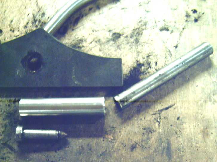 "Telecoping" compactor to make
"tall donuts" of
electrode material.
The inside of the large tube is the outer diameter of the donut.
The bolt fits in the bottom to form the hole for the carbon rod.
The smaller tube fits inside the larger and over the bolt,
and is pressed in to compact the material.
The hole in the plate is just slightly larger than the inner pipe.
The piece is pressed out of the pipe through the hole.
Ha ha.
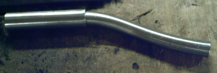 At 3 tons the pressure stopped
going up. The
inner pipe was bending over.
And the pipe ends mushroomed a bit.
Apparently something heavier than "light" stainless steel pipes is
required?
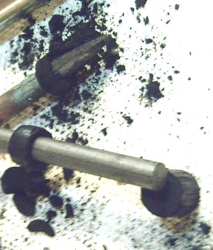 Later with small improvements
& just 2 tons
force, I successfully
made a small "donut" of compacted nickel-manganese-oxide mix
that fit smoothly on a 5/16" carbon rod. (Another on the tapered
3/8" rod behind started breaking because the inner hole was 5/16".)
The solid cylinder at the bottom, with a bolt turned on the lathe
for a plunger, was successful but it would break up if drilling a
hole in it was attempted. (Rats)
2 tons seemed to be exactly right - at least for my
equipment and the size of the donuts. Any less and the donut crumbles
(I'm sure there's a pun there somewhere). Any more and the stainless
steel pipes start to bend. With the small surface area of the donut
hopefully it's about right for the electrode. (Calculated density of
the compacted nickel-manganese oxide based on the measured dimensions
and weights is about 1.9 g/cc, which is probably a bit under ideal but
in the right ballpark according to literature.) I discovered that
luckily the small donuts slide easily off the inner bolt and onto a
carbon rod. Yay! (I hope they make a good connection to the rod!)
Now to make the next electrode I need to make new
separator papers and a new tube, and it's high time to end this 'July'
report (August 8th). I think I'm on the right track.
DC Wiring Demo Panel
In addition to continuing to wire the cabin, I decided to
make DC demo panel for the Swilawiid green energy conference in
September. It progressed in a couple of work sessions. As I made it it
occurred to me that it was just about the same as actually wirng the
cabin except the wires were shorter.
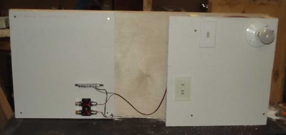 Sample house circuits on "wall"
at right;
"Wiring closet" wall mounting of equipment at left (gyproc for
fire safety, over plywood to hold screws securely) starting with a
couple of surface mount circuit breakers and a ground bus bar.
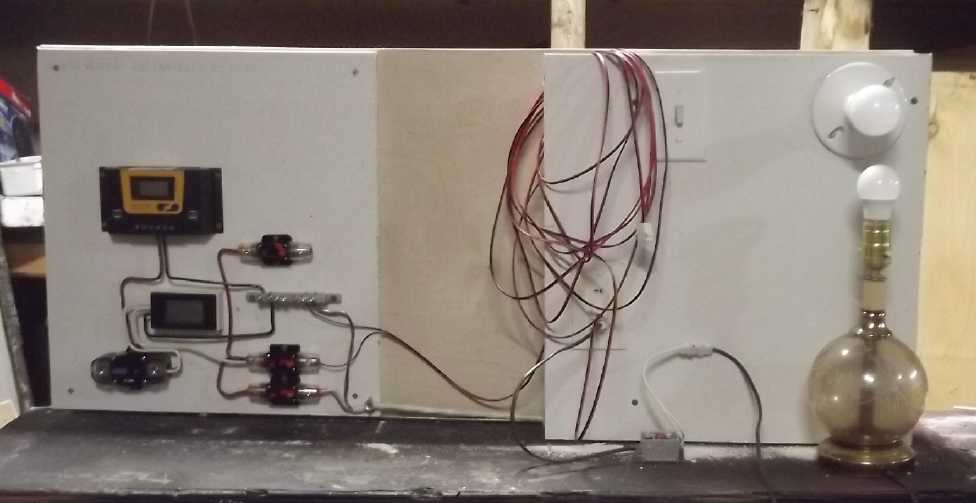 Added charge controller and power
monitor,
"main" battery circuit breaker,
a 12V lamp plugged in with DC to DC down converter.
Cabin Construction & DC Wiring
This is mostly covered in the feature article as well as
the detailed report in "Other Green Projects". Here is the brief view.
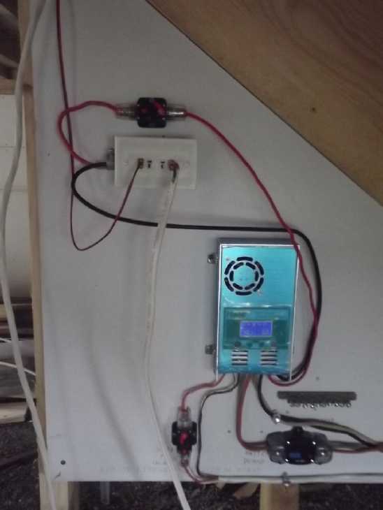 I continued adding to the surface
mounted wiring board. I installed the ground bus made in June. I 3D
printed a four-outlet wall plate to plug
several ceiling lights into rather than hard-wiring them. I suppose one
could fit 5 or 6 T-sockets on one wall plate. No "power bars" to get
enough outlets!
This box/plate is on
the charge controller's "output" circuit, which is set to shut off if
the battery gets the least bit low - which would probably be from
leaving too many lights on in the winter when solar power is scarce.
36 V DC Wall Receptacle
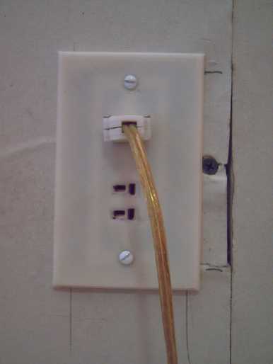 On the 10th I wired up a wall receptacle in the upstairs room. I took
off a piece of gyproc from under the window and screwed in an
electrical box. Underneath, the walls are still open and stringing the
wire through the 2 by 4s by drilling holes was easy.
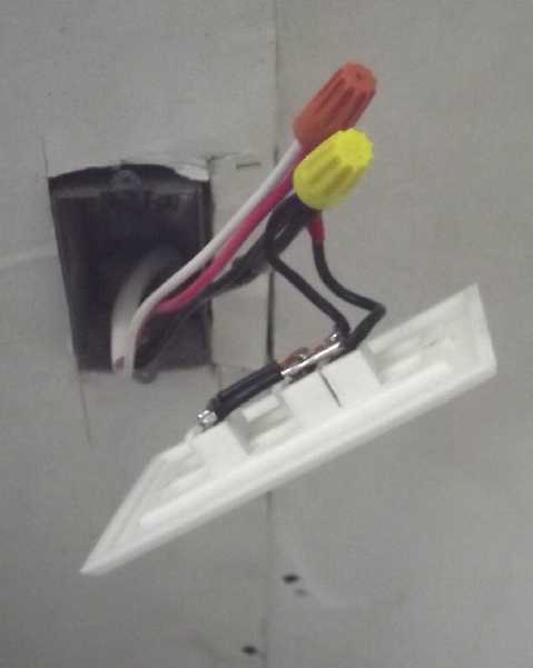 I used #14-3
cable, which is actually four wires counting the #14 bare "ground"
wire. I tied red and white together ("+"), and the black and the
bare after insulating it (two blacks, "-"), and tied them to the
pigtails soldered onto
the T-Plug (36V DC) wall plate. Double #14 AWG is the same as #11 -
good for about 25 amps. #12-2 (rated 20 amps) would be fine for 36 volt
- 20 amp outlets, too. #14-2 is a bit thin.
Enclosing wire joins in metal electrical boxes is still a
good idea. 36V may not electrocute, but arcs and sparks or heat from
poor connections, can still start fires if next to something flammable.
(But no need to ground the box.)
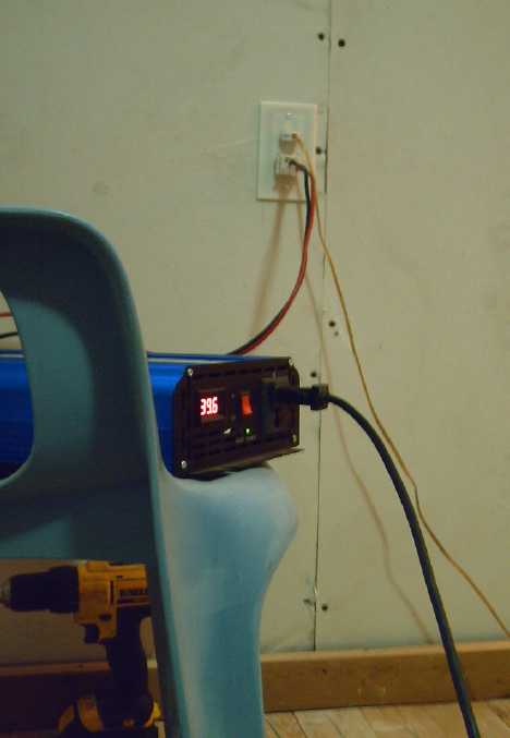 In early August I used the new outlet and a "double T-Plug" I made a
while back to power a
2500 W PSW inverter (36 VDC to 120 VAC) and vacuumed the room on
solar/battery power. The
double plug wanted to pull out at the slightest stress on the heavy
wires. (The "giant T-Plug" for
high currents is the real answer... but they need to be manufactured.)
Most vacuum cleaners are somewhere near 1500 watts.
Theoreticly that
should have blown the 20 amp (36V) breaker with around 40 amps. In a
brief run it didn't. I used a vac that had 'up' & 'down' buttons to
increase or decrease
power & suction. At full power the inverter (2500W?!?) balked after
about half a
minute, quitting and saying "Fault", but if I turned the vac to setting
3 of 5, it ran fine and I did the job.
In
Passing
(Miscellaneous topics, editorial comments & opinionated
rants)
Scattered
Thots
What Makes an Inventor?
* What is it that makes an inventor? "IQ" and "Cognitive ability" are
certainly measures, but I think it's "associative ability" that sets
inventors apart. That's the mental quality of seeing "obscure"
connections between things that are apparently unrelated.
Just for example, in open loop air heat pumping, how are
indoor-outdoor heat exchange ventilators related to compressing air (or
refrigerant) to pump heat? These have always been separate, unrelated
concepts and systems. But it's combining the two that is the key. The
compressor heats already passively warmed air coming from outdoors,
radiates heat to the room, then sends it (still slightly warmer than
the room, still compressed) into the indoor-outdoor exchanger to cool
by warming the incoming air, then it decompresses (through a turbine to
extract even more energy) and finally it exhausts outdoors colder than
the outdoor air. The combined system should give a coefficient of
performance that heat pumping "experts" would deem "theoreticly
impossible", perhaps 10 to 1 or better, eg, 5000 watts of heat from 500
watts of electricity, even at freezing outdoor temperatures. (I must
get back to that project!)
I was once profiled as being in the top 1% of the population in
"associative ability". Others doubtless have more balanced or other
leaning mental abilities, but that one is surely what marks inventors.
Then of course, to invent one must begin to REALize the
concepts. It
is an iterative process where starting by DOing one thing, even
without a complete or concrete idea of what the result will be. This
causes more dots to connect and the creation to
improve. Back to the example, the first idea was that if an air
compressor compressed room air, it wouldn't have to heat it very much
to have it run a heat radiator, so the COP could be high. But how could
room air heat room air? The cooled air from the radiator, having
actually lost heat to the room, would be much cooler once it was
decompressed and would have to be vented outside. So cold air would
have to come from outside to replace it. At that point in the idea, it
sounded like it might be a "zero sum game". There some might think
"Yeah, that figures!" and go on to something else.
But while still compressed, that air still has compression
energy. So came the idea of having it somehow help to spin the
compressor - "ROVACS" and other compressor-decompressor ideas, "ending"
(as far as the concept has gone so far) with the idea of having it turn
a turbine that mechanicly helps turns the compressor. (probably by
being on the same shaft)
Also this compressed air from the radiator unit is still a
little warmer than the room air - more "waste" energy! The idea of the
passive heat exchanger came to me along with the other while putting
together the basic "compressor plus radiator" unit. Most of this
evolving concept can be seen in TE News issues from about January to
April 2020, with conceptual improvements to the rotary compressor, and
then the decompressor turbine idea, in more recent issues.
AC Body Voltage Levels
* It seems to me - speaking only for myself - that the ringing in my
ears is only just starting to fade perceptibly after 8 hours sleeping
in my
"Faraday cage" cabin (without AC wiring and where I generally measure
AC body voltages under around 15mV). And "perceptibly" is only because
I'm listening for it. But it gets louder again in under half an hour in
the house. (...where fields are mostly well over a volt and again
because I'm listening for it.) I might almost say - for me - "days to
fade, minutes to resume". If others are experiencing anything like
that, it's no wonder it's little understood where tinnitus comes from
since nearly all of us are so rarely out of electric AC voltage
gradient fields for any length of time.
The conductive fabric tuque/beanie actually helps more than I realized,
but it's not the same as just being away from electric fields. I didn't
realize how much it was helping until the day I washed it and set it
out to dry. The ringing was much worse after a day without it -- back
to how it used to be. Even overnight in the cabin only brought it down
somewhat. The tinfoil over the car's sun visor also seems to reduce the
ringing I notice after highway drives.
* I was guessing that the AC induced body voltage may tend to
cause tinnitus if it is over 20-50mV. One night in the cabin I felt by
3 AM the ringing didn't seem to be fading at all. It felt like my ears
were still "under attack". Why should that be? I had been working on
the siding and had plugged the angle grinder into the cord that ran
around outside the building. But I had brought it in in case it rained,
still plugged in. There was about 10 feet of energized cord on the
ground about nine feet directly under my bed. A meter said it was just
around 40mV of body voltage lying on my bed. Apparently that was enough
to be a problem! I unplugged it and it was still over 20mV coming from
the few, short cables with the plug-in grid ties in the corner over 20
feet from the bed. If 40mV was noticeably too much, even 20 probably
was having a mild but continuous deleterious effect. I unplugged the
building - the one plug in the far corner - and tossed the extension
cord outside. It went down to around 5mV.
Of course that's just me. I'm not sure where it might
start for others and for those most affected. Some are doubtless
unaffected for years at much higher levels, but it's starting to look
to me like many or most older people have ringing ears. It's just not
talked
about unless I bring up the subject. But I think the Greenhome
Institute is right: "no exposure" is under 10 mV, not 20 or 50 mV.
Greenhome Institute gives the following induced AC body voltages for AC
electric
field exposure:
0-10mV - no exposure
10-100mV - mild exposure
.1-1V - strong exposure
over 1V - extreme exposure
Induced AC Body Voltage is easily measured by connecting
one
probe of an ordinary AC voltmeter (precision preferably to .001 V AC)
to ground, wetting one's thumb and
finger, and gripping the other probe, and not moving during the
reading. (Don't touch the ground connection.) Ground may be actual damp
ground or the grounding pin of a power socket (can be an extension cord
ground pin). Position is important in stronger fields. Outdoors at
least, measured voltage is much higher when standing up than crouched
or sitting.
ESD
(Eccentric Silliness Department)
* In their protracted march of capturing or liberating (depending on
your point of view) Donbass towns and villages one by one (...more like
"liquidating" them where the fighting is hard), the Russians have
achieved pobieda (victory) in Pobieda, have progressed through
Progress, and now are in the middle of New York. (Wait, what?!?)
"in depth
reports" for
each project are below. I hope they may be useful to anyone who wants
to get into a similar project, to glean ideas for how something
might be done, as well as things that might have been tried, or just
thought
of and not tried... and even of how not to do something - why
it didn't
work or proved impractical. Sometimes they set out inventive thoughts
almost as they occur - and are the actual organization and elaboration
in writing of those thoughts. They are thus partly a diary and are not
extensively proof-read for literary perfection, consistency,
completeness and elimination of duplications before
publication. I hope they may add to the body of wisdom for other
researchers and developers to help them find more productive paths and
avoid potential pitfalls and dead ends.
Electric
Transport
No
Reports
Other
"Green"
&
Electric
Equipment
Projects
Some
Thoughts
on
DC
Houses & DC Appliances
36 V DC is the optimum voltage for most
in-home/in-building wiring.
IMHO. Since the electrification of everywhere a century ago we have
become so used to wiring with 120 VAC
everywhere (230V in much of the world) that we never think of doing it
any other way. The idea it's less than ideal and the whole thing ought
to be re-thought will probably come as
a shock to most people. The advantages of 36 volts DC haven't been
thought out by most
of us, but working with solar, and then discovering health reasons, I
was gradually led to this
logical conclusion and am wiring my cabin with it instead of 120 V AC.
What's good about it?:
1. DC doesn't induce oscillating electric fields into the body, which
may cause
tinnitus, ongoing vague feelings of stress and unease, and other health
effects whose cause is usually unrecognized. (See
GreenHomeInstitute.org
for more on this topic.) So AC wiring is to be avoided where practical,
including AC generated from a DC system with an inverter. Runs of AC
wiring should be kept very short and few, or made with shielded cables
and
cords, or run inside (grounded) metallic conduit pipe. In theory, it's
easy to avoid the need for AC except for higher powered equipment.
Lighting in particular is now very low power with LED's, which emitters
are already DC, and it is almost absurd to run 120 or 240 V AC wiring
to then be reduced to low voltage DC at the fixture or "bulb".
2. 36V DC nominal is the highest electricly "safe" voltage.
Electrocutions from
36V and below are not unheard of, but they are very rare. 48V DC or
higher building wiring would come with some electrocution death
statistics, as do the present 120V and 240V AC. (Think that if three
12V batteries
are under charge at 15V, nominal 36V would hit 45 actual volts, and
nominal 48V with four can reach 60 V. High DC voltages can be more
dangerous than AC.)
3. Line losses at 36V are much lower than with 12V, and substantially
lower than 24V.
Wire gauges for higher power appliances at 12V are huge. Consider
running an electric heater/kettle/toaster/burner of 1000 watts. This
requires a circuit of: 12v = 83 amps = #4 AWG wire = very heavy and
unwieldy; 24v = 42 A = #8
wire (better, #6); 36V = 28 amps = #10 AWG wire = much more managable.
(For off grid
situations, one probably would only use such high power for short
intervals, EG boiling water for coffee or tea, heating something in a
microwave or on a stove, vacuuming...)
4. From 36V it's easy to get any lower voltage, such as 12 or 24V for
12 or 24V DC appliances. There are low-cost (5$?) 20 amp screwdriver
adjustable DC to DC converters to go from any voltage up to 40, to any
lower voltage. These - just one device - can replace most any and all
"wall
wart" 120V AC to DC power converters to power a multitude of electronic
devices. And there are even cheaper ones (2$?) with lower current
ratings. So there would seem to be little reason to go to lower voltage
wiring across a home or building. (Prices are for the
electronics board only - as currently manufactured, 36V plug & 12V
socket, case (3D printed?) need to be added.
5. Ease of Mind. No worry about getting electrocuted by touching a
damp power cord in the rain, laundry or bathroom, or by flipping a
light switch with wet hands. Kids aren't going to shock themselves by
touching the wrong thing.
6. Today there are confusing choices for DC power of 12, 24, 36, 48
volts and
beyond. It is important to establish a "standard" wiring voltage for
DC in order to induce manufacturers to mass produce DC appliances. 36V,
while presently somewhat overlooked, is the best voltage to do that for
the
reasons above. It should be encouraged, promoted and adopted in new
power & building projects. It's only an uphill struggle until
there's enough momentum to reinforce the logic of it, then everyone
will jump aboard.
 I myself have "adopted" T-Plugs/T-Sockets (AKA Deans Plugs) as the
standard for 36V house wiring. I have 3D printed triple and quadruple
wall receptacle plates, plug and socket shells and more to facilitate
adoption of 36 V. They should be good for up to 20 amps. ("Plus" is the
"cross" blade on the right in the image.)
(I do recommend an improved version T-Plug be manufactured with 10mm
long blades instead of 8mm, because they are too easily pulled out of
the socket. Also other choices of plug styles are needed besides with
"solder pads" to attach wires to the plugs.)
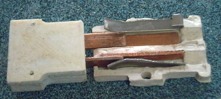 And I created
a "giant T-Plug" & Socket for currents to 50 amps. These are harder
because everything is made from scratch - they need to be manufactured.
But manufacturing keeps getting easier as new techniques and tools are
created. (...and I must upload all the 3D print designs to
thingiverse.com for all to use!)
Various power supplies can
be had to convert 120V AC from
the power company to DC. Of course, DC is an even better choice for
"off grid" wiring compared to 120V, which requires an inverter that
itself uses extra power. Lithium-iron phosphate
batteries (LiFePO3 - 12 cells) with a "balance charger" attached
presently seem to be the best and safest choice, now available with
ratings in hundreds of amp-hours. "Golf cart
batteries" or other Pb-Pb cell costs are rising and they have much
shorter life spans, while the price of LiFePO3 has come down
substantially and is still dropping. (With those, "36V" is generally
close to 40 volts if
they are charged, and I'm tempted to call LiFePO3 systems "40V" instead
of "36V". I think it sounds better! They can be charged to 42+ volts at
room temperature, but little energy is gained, they drop to ~40V at low
temperatures anyway and DC to DC converters are mostly rated only up to
40.0 volts.)
Having created wall outlets for 12 VDC ("micro T-Plugs"
& sockets) and 36 VDC ("T-Plugs" & sockets), and with wiring
the cabin for 36, I thought I'd look for DC appliances to match. Being
that there is no "consensus" DC wiring voltage, the confusion of
choices from 12 to 48 volts and beyond has made manufacturers hesitant
to make DC appliances.
Note for 24V DC: With no "standard" wall receptacles, sockets or
plugs being available, the 36V T-Plug outlets, cords and plugs could
well be used for 24 V as well. A number of useful circuits such as LED
"light bulbs" and DC to DC down converters to make 12V can be run from
either voltage or in between. It does however make a "user beware"
situation since one could easily plug in a 24V appliance into 36V or
vice versa, possibly destructively.
Lighting
This lamp
works the same,
looks the same as any other but
has a DC LED bulb, "T-plug" plug, and runs off 36 V DC
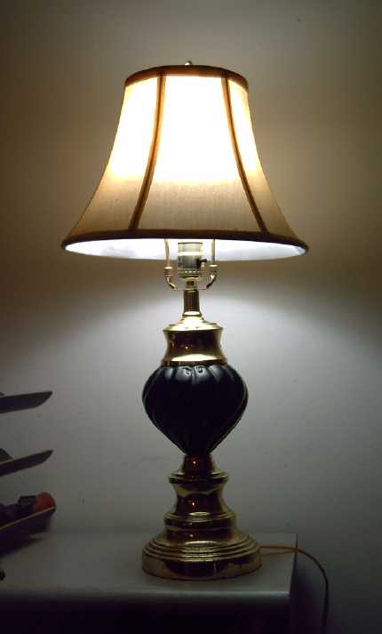 Now that LED's
have replaced most other
lighting technologies, DC lights are simple. LED's
are inherently low voltage DC components (generally 2.9V for lighting
LED emitters. A fast, simple way to get nice DC lamps is to take a nice
AC lamp, cut the plug off, and put on a 12V or 36V plug. Then one buys
a DC LED "light bulb" that screws into a regular ("E27") lamp socket.
There are "12V" bulbs, and there are "12 to 72V" bulbs, which are
ideal at 36V. (Note: These last are dimmer - lower power than labeled -
when run
at 12V.)
There are various 12V LED
lights (for automotive, marine,
off-grid...) which can be run off 36V using an adjustable DC to DC
converter set to 12-14V output. (A 20 amp adjustable DC to DC down
converter running off 36 or 24 volts can replace any "AC Power
Adapter".)
I bought some beautiful, bright, 30x60cm (1x2 feet) flat
LED light panels that work admirably at 36 volts, with just a 5Ω
resistor to limit the current and set them near or under their 24 watt
rating.
Blue emitters for LED lighting were invented in the 1990s
by a Japanese man (I forget his name) who pursued it for decades even
after everyone else had
given up. Without him we would still be using incandescent and
fluorescent lighting. His Nobel prize was well earned. They make
lighting colors
the same way fluorescent tubes do, by shining the single frequency LED
emitter on a phosphor that glows in a broad spectrum centered at the
desired color temperature. But unlike fluorescent lights, they don't
have a
strong spike of retina-degrading intensity at the mercury vapor arc
wavelength that comes right through the phosphor, and so they are far
more pleasant and beautiful. And incredibly efficient, requiring
perhaps 10-15% as much power as an incandescent light bulb of
equivalent brightness. Typical "color temperatures" (in degrees Kelvin)
available for LED lighting of any style include:
2700°K - orangeish/warm
3000-3300°K - yellowish/"warm white"
~4000°K - "neutral white"/mid-spectrum (sometimes seem faintly
greenish IMHO when seen next to yellowish & blueish. My favorite
for most lighting)
5000+°K - blueish/"daylight" (plant lights; some like even 6000K
for work
lights)
Wiring specificly for DC LED lighting (ie, wires not going
to
outlets or heavier loads) need not be heavy. I'm using #18 AWG speaker
wire. It looks patheticly thin, but #18 is rated for at least 5 amps,
and even
a bright 36 watt LED light draws only 1 amp. It's easy to run and
cheaper than heavy house wire. (I do wish I had a cable stapler for it
- even simpler.) For 36 volts, insulation need not be heavy as it is
with #18 "lamp cord" wire.
Fridges, Freezers, Washers, Dryers, et Cetera
For such actual high powered appliances, the pickings seem
quite slim. The are 12 & 24 volt fridges, freezers, washers and
dryers, but the usual price tag of several hundred dollars has a 1000
or 2000 $ amount added on the front. There will surely come a day when
36 volt
units with highly efficient BLDC motors will come on the market for
similar prices as 120/240 volt AC units, but
it's not yet. I did however buy a 24 volt BLDC deep well pump for just
300+$ - a bargain for any deep well pump - so there is progress. DC
power tools aren't available except those that have
their own battery - which is more convenient than a cord anyway when it
works for
your work.
Accepting a DC to AC inverter with its small but extra
continuous power
draw and what may someday be called "legacy" AC appliances seems to
be the only practical route today. One can of course turn off the
inverter except when an "on demand" use appliance is to
be used (ie, vacuum cleaner, not fridge or freezer), and if the cords
are kept short, they will generate little EMF
into the space except near and between the inverter and the
appliance(s).
Of course, having 36 V wall outlets doesn't preclude
running 24 or
12 volt appliances such as fridges and freezers by using a DC to DC
down converter "power adapter". But IMHO appliances would be better
made with 12 & 36 volt options rather than 12 & 24. Or be made
more flexible to handle 24 to 36 volts supply.
Electric Heaters
Electric heaters and hotplates having nothing but a
resistance heating element and mechanical switching controls can be run
at their
rated voltage or any lower one. At 38 volts, each unit will run at
1/10th of its 120 volt power rating. So a 1500 W heater will run at 36V
as a roughly 150 W heater.
I made a little "cheater cord" (from an only extension
cord) with a 36 V T-Plug on the end, to plug such appliances into 36 V
withut chopping of their regular plugs. This past spring I was heating
my bedroom at night
with two or three such heaters: 150, 80 & 50 watts - just about
200, 250 or 300 W on the consumption meter. The 290 AH, 36V battery is
recharged daily (usually by around noon) by five solar panels. This
certainly isn't enough heat
for winter, and the solar panels probably wouldn't charge it back up
daily in winter with this large all-night drain, but it's good in the
"shoulder seasons" when one only needs a little heat.
Okay... On AliExpress I've found low cost 12/24 V electric
heaters. Some are portable car heaters/window defoggers. There might be
some suitable; I'd have to check further. A 24V heater run at 36V would
be 2.25x the rated power and might burn out. A 48V heater run at 36V
would be 56% of the stated power. They seem to offer similar lower
power ranges to those I've been using.
Hotplates/Stove Burners
I put a cup of water in a pot, put it on an "1150 W, 120
V" simple burner hot plate, and plugged it into 36 V with a "cheater
cord", making it only ~115 watts. It took the better part of an hour
before the water was simmering softly. It's just not enough power - it
takes so long that much of the heat is radiated to the room while the
water is heating.
But I do see 12 & 24 volt hotplates ("DC Stoves") of
several hundred watts on AliExpress. There was a single burner
induction cooker "12/24/48 V". There was just one model, so it would
almost doubtless work also at 36V too. It looked promising as induction
transfers the heat really well to the pan (which has to be magnetic
metal), but it was over 200$C.
Hot Water Heaters
A 3000 W, 230 V water heater plugged into 36 volts would
heat unbearably slowly, at under 3% of its usual power. My own house
hot
water tank is powered by 120 V instead of 240 and is hence 750 watts
instead of 3000. When I turned it off and went away for a week, it took
8 hours to be hot enough for a shower. Except for that, with one or two
people I have never
been short of hot water. By using a lower power, if I use hot water
during the day, there's often enough power (ie, 750 W) coming from the
solar panels
through the grid ties that it's being reheated from them instead of
much of it coming from the power company. Water tank elements for
various low voltages are available too (eg, "Dernord" elements). I have
a 15 liter "under sink"
tank presently with its original 1200 W, 120 V heating element. At 38 V
that would be 120 watts. That will eventually heat the tank, so it
works well provided you don't need to use the hot water often, or use
more water than is held in
the tank. (I un-installed it from my kitchen owing to a well water
chemical issue - the hot water reeked.) At one time I had changed the
element for a 36 volt one (it had 3 x 400 W elements), but found 1200
or 400 watts was a bit much for my solar system with small batteries at
the time, so I ended up at around 150 W anyway by putting the three
elements in series instead of parallel, or 200 W with two in series.
One should be able to come up with almost any desired wattage range.
Cabin Construction & DC Wiring
Main Wiring Board/Closet
 I
continued adding to the surface
mounted wiring board. I installed the ground bus made in June. I 3D
printed a four-outlet wall plate to plug
several ceiling lights into rather than hard-wiring them. I suppose one
could fit 5 or 6 T-sockets on one wall plate. No "power bars" to get
enough outlets! This box is on
the charge controller's "output" circuit, which is set to shut off if
the battery gets the least bit low - which would probably be from
leaving too many lights on in the winter.
A problem I've run into is that I
always want to have a negative ground, but in most charge controllers
it's the negative side that switches, both for the solar panels and the
load output. They are "positive ground". The reason for this is that
n-channel MOSFETs are better for switching power than p-channel, so
it's easier or cheaper to manufacture. That doesn't mean it doesn't
create headaches. Does one ground the solar panels, the batteries, or
the main ground bus? What about the lights on the low-power switch-off
circuit? They can't be grounded.
The 36 volts "+" stays live when it's off, and the "-" becomes 36 volts
as well. If it was higher voltage it could be dangerous.
36 V DC Wall Receptacle
 On the 10th I wired up a wall receptacle in the upstairs room. I took
off a piece of gyproc from under the window and screwed in an
electrical box.
DC Wall Outlets/Wiring: Wire Colors and Connections
Since AC wiring uses different colors than DC wiring and
is the most commonly available wire, there is often no red wire. (What
bozo decided black should be the "hot" wire in AC wiring, anyway? It's
the color of no energy, of earth, absorbing all light -- and somebody
made it "hot"?!?)
For DC wiring we'll stick to black, or bare or green per
AC standard, for negative or ground. If using a bare wire, be sure it
can't short to anything.
The other normally available color is white, so that will
have to substitute for red in many situations. If deviating from this,
wires should be wrapped with colored tape to make their usage clear.
Black, bare, green: minus
Red, white: plus
What is the purpose of grounding the metal box with AC
wiring? My understanding is that it is so that if a "hot" wire touches
the box, it will blow the circuit breaker to avoid a shock hazard if
the box or a screw is touched. At 36 volts, there is no significant
shock hazard, so it's better to leave the box unconnected. If a +36V
connection (and no other) touches the box, no harm is done and the
breaker isn't needlessly blown.
As I see it, there are two distinct types of circuits for
DC wiring: "LED lighting only" circuits and "other appliance" circuits.
"Other appliances" using considerable power may need heavier wires than
for 120/240 V AC. (And allowing thinner wires is the main reason such
high voltages are commonly used.)
A single LED light of 24 watts is a pretty bright light,
yet the current to drive it at 36 volts is just 2/3 of an amp. Even
light #18 AWG "lamp cord" will handle 5 amps - enough for any typical
lighting. Plus, with no need for higher voltage insulation, even #18
"speaker wire" is fine. (Note: Watch out for cheap non-copper speaker
wire. It is coated to look like copper wire, but the resistance is much
higher. Silvery color on cut ends betrays this "fake" wire. Even that
is probably sufficient for a lower power LED light or two.)
Wires for outlets or other applications that will or might
have higher power appliances connected need much heavier wires. (But
not so heavy as for 24 or 12 volts!)
We don't really know what appliances are or will become
available for 36 V DC power supplies. (We do know that 36 V DC can be
converted to any lower voltage for lower powered circuits with a low
cost power adapter, and that there are some 12 to 24 volt appliances
presently available. And or course 120 V AC appliances can be run with
a DC to AC inverter. 36 V to 120 V inverters are available.)
We typicly run circuits at up to 85% of the circuit
breaker current. #14 AWG wire running 12.5 amps at 120 volts is 1500
watts - the heaviest appliances commonly plugged into a 120 V AC wall
outlet. That current at 36 volts is just 450 watts. That's just enough
for a toaster, kettle, hot plate, microwave oven or coffee maker, or a
vacuum cleaner, but it will be a slow one. #12 wire (w. 20 amp breaker)
or heavier is preferable for wall outlets. Running 17 amps at 36 volts
would give appliances of just over 600 watts.
#10 wire (rated 30 amps, 30 amp breaker) allows 25.5 amps,
allowing just over 900 watt appliances.
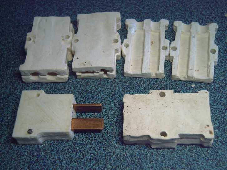
 Appliances over 1000 watts will need #8 AWG wire and heavier plugs,
like the "high current T-Plug" & socket I made just samples of by
hand some years back. ( TE News
#161 ) To my chagrin the size specs are (presumably) in some
earlier issue I didn't readily locate. They are: blade protrusion, 2mm
x 8 mm x 15 mm; spacing between blade centers 12mm, making a 7mm gap.
3D printed nylon socket bodies should be acceptable. As I
didn't have nylon print filament when I was doing them, I made them of
porcelain. (On the plug the contacts are outside. On the socket they
are inside and heat from a poor connection could melt many plastics.)
(I really must upload all my designs to thingiverse.com for anyone to
use!)
 Most off-grid installations will have
trouble supplying such higher-powered devices for extended periods. (Of
course "on grid" buildings could use the AC to drive a heavy 36 V DC
power supply and run all the DC things they wish at low voltage DC.) It
is especially desirable to keep AC wiring away from bedrooms (along
with WiFi and cell phones) for health reasons. Many people don't give
their bodies many breaks from such mild but eventually deleterious
emissions.
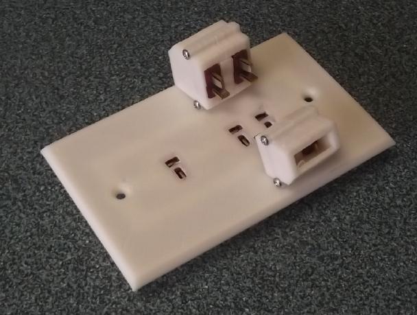 I
also made a "double T-Plug" idea for heavier circuits, maybe 15 or 20
to about 30 amps. I thought it would be good because it uses the same
T-Plugs & Sockets. Frankly I don't think I recommend this, but it
consists of two T-Plugs/T-Sockets beside each other exactly 12mm apart.
I spaced some wall outlets that way and made shells to hold the T-Plugs
at that spacing.
I
also made a "double T-Plug" idea for heavier circuits, maybe 15 or 20
to about 30 amps. I thought it would be good because it uses the same
T-Plugs & Sockets. Frankly I don't think I recommend this, but it
consists of two T-Plugs/T-Sockets beside each other exactly 12mm apart.
I spaced some wall outlets that way and made shells to hold the T-Plugs
at that spacing.
The "giant T-Plug" is a better idea.
 In early
August I used the new one upstairs in the cabin to power a 2500 W PSW
inverter (36 VDC to 120 VAC) and vacuumed the room. The double plug
wanted to pull out at the slightest stress on the heavy wires. (This is
why I wish the T-Plugs had 10mm blades instead of 8mm, but it would
have only been somewhat better. The "giant T-Plug" for high currents is
the real answer... but they need to be manufactured.)
Most vacuum cleaners are somewhere near 1500 watts.
Theoreticly that should have blown the 20 amp (36V) breaker. I had a
lower powered shop vac (850 W), but also a vac that had buttons to
increase or decrease power. At full power the inverter (2500W?!?)
balked after about half a minute, quitting and saying "Fault", but if I
turned the vac to setting 3 of 5, it ran fine and I did the job.
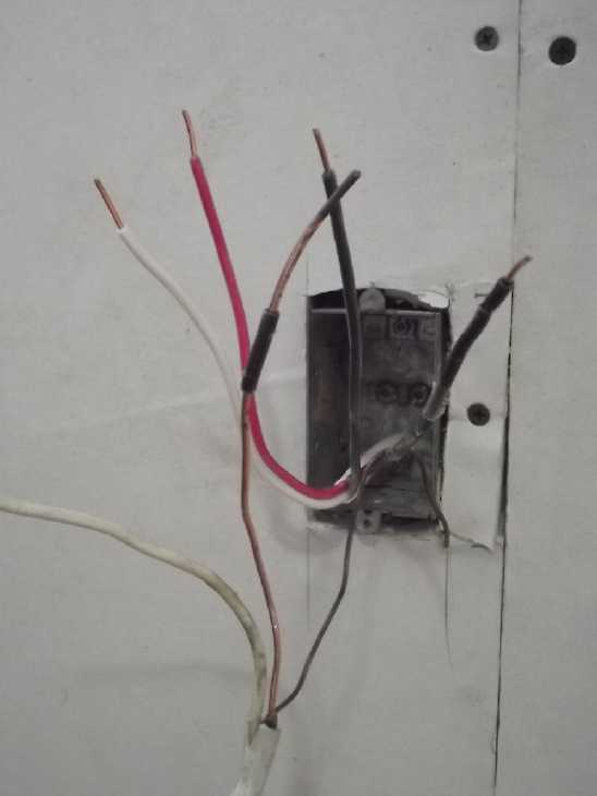 For said wall
outlet I ran a #14 AWG - 3 wire cable from the DC "wiring closet" under
the stairs straight to the outlet box. Since the bare "ground" wire is
also #14, that makes four wires. The way "AWG" works, the diameter of a
wire is half of one three gauges down. This means that two #14 AWG
wires together have the same cross section as a single #11. Best
breaker rating for #11 would be 25 amps, allowing up to 900 watt
appliances to be plugged in.
I may want to run a low wattage electric heater at night
or potentially an inverter to run an AC vacuum cleaner. (I have a lower
powered 850 W shop vac. Many vacs need a full 1500 watts.)
I insulated the bare wire by stripping pieces of black
insulation from a scrap of #12 AWG wire (seen in front), which are just
a little fatter than #14 and slip on easily.
 I tied red and
white together, and the two blacks, and tied them to the pigtails of
the T-Plug (36V DC) wall plate.
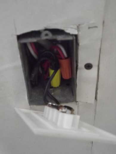 I used a
moderately deep box for the wires plus the sockets to fit into.
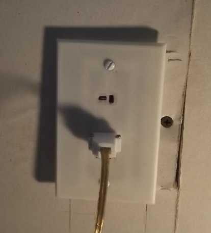 When I put the
wall plate on I discovered the box stuck way out of the wall. Oops!
 It worked but
after a couple of weeks I took the crumbling piece of gyproc off and
moved the box back. Still not quite flush. But much better. (How
can it be crooked when it's screwed to the wall stud, top and bottom?)
Cabin Construction
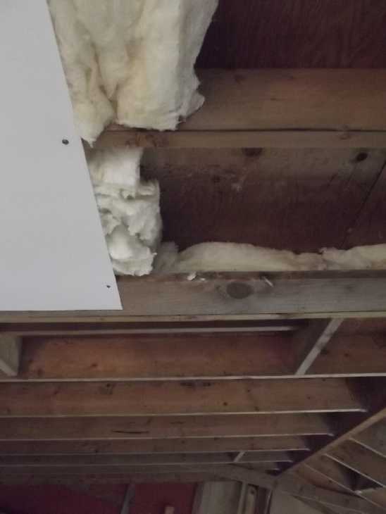 The end of the second set of ceiling sheets didn't quite
reach the last rafter, with this one central rafter gap being more than
24 inches wide. What to do? I finally opted for screwing in a 2 by 2
onto the side of the rafter an inch above the bottom, then screwing a 1
by 8 to that, horizontal, so it was flush with the bottom of the
rafter. That gave
10 inches width to screw ceiling panels to.
Horrid Fiberglass
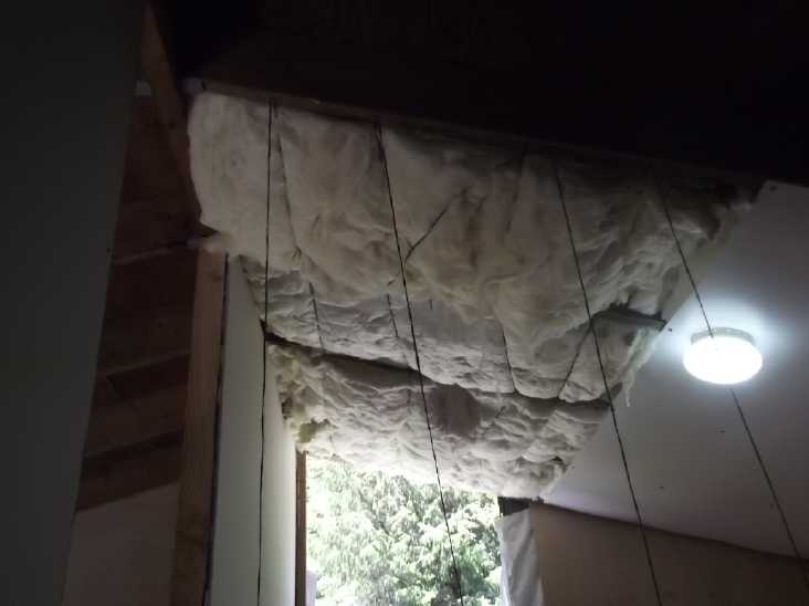 [14th] I
finally got the nerve and put on crappy old clothes to
continue insulating the upstairs room ceiling. It was even worse than I
expected. I finally used the last loose pieces of R28 insulation I got
used, but the "new" bag was just as bad. It was hard to tell where one
so-called "batt" ended and the next began - they all just stuck
together almost as if one big fat piece. Whenever it was touched,
clouds of very fine dust came off it, and bigger bits continually fell
off like snow. Not only would it not stay put in the ceiling spaces
between the rafters, but it would hang from a string like a limp towel.
In the lower parts I could put in strips of plastic and then slide the
"batts" in, but I had to string the top part. I used some old twine and
roofing nails to hold it once in place.
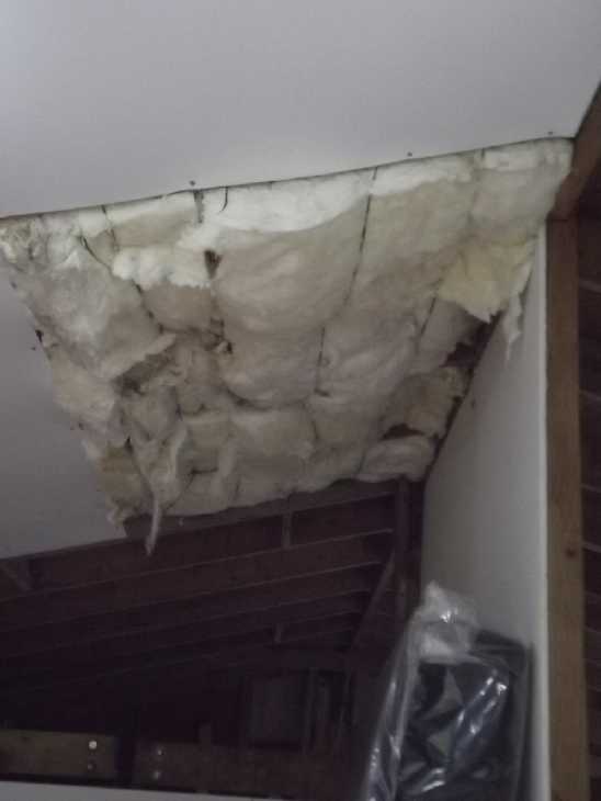 This
particular
insulation reminded me of some from 1976-77 when manufacturers had
decided to used "recycled glass" to make fiberglass. It turned out that
many fibers were the same shape and size as asbestos, hence were
carcinogenic. I had used that horrid stuff under my house in
1977-78, and this "new" stuff didn't seem any better. What luck! Hmm...
had it lain around all these years since that period? I
finally thought to look for a URL on the packages. If there wasn't one,
it could potentially be that old. There wasn't, but there was a date:
Dec. 2001. Maybe it had degraded over a couple of decades of imperfect
storage?
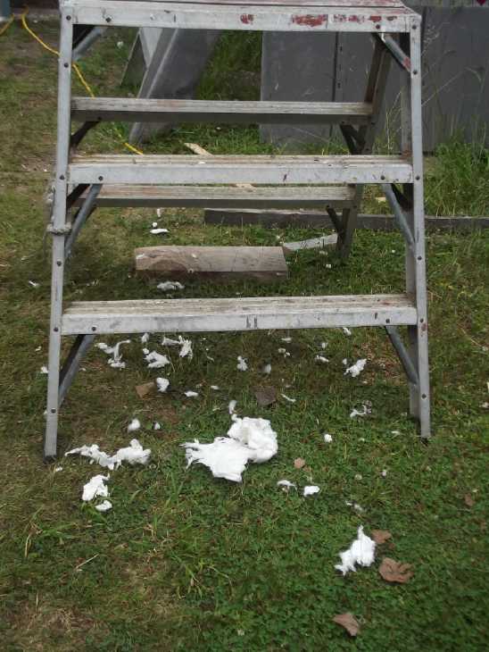 I had to vacuum up the "snow"
that fell in
simply cutting
one batt into four short pieces with a clean, sharp knife.
I tried my very best to get almost any nicer insulation
than fiberglass. I finally decided dried lawn grass (~R3 per inch -
investigated in TE News #170
& previous, two years ago) just wasn't good enough for the walls,
no
one in northern BC would sell me common cellulose fiber loose fill (R4
per inch), and nice looking organic fiber batts (cellulose, wool...)
that I saw on line in Europe likewise aren't to be had around here. The
only
other choice is mineral wool batts, which cost substantially more
instead of less. So I ended up with
fiberglass, bad enough any time, and someone who was moving sold me his
old R28 batts for the ceiling, cheap. (It wouldn't have been so bad
under the floor, or at least in the walls! I'll have to seal the
ceiling
really well.) I opened a "new" bag for two more batts and found big rat
holes in them. Yetch!
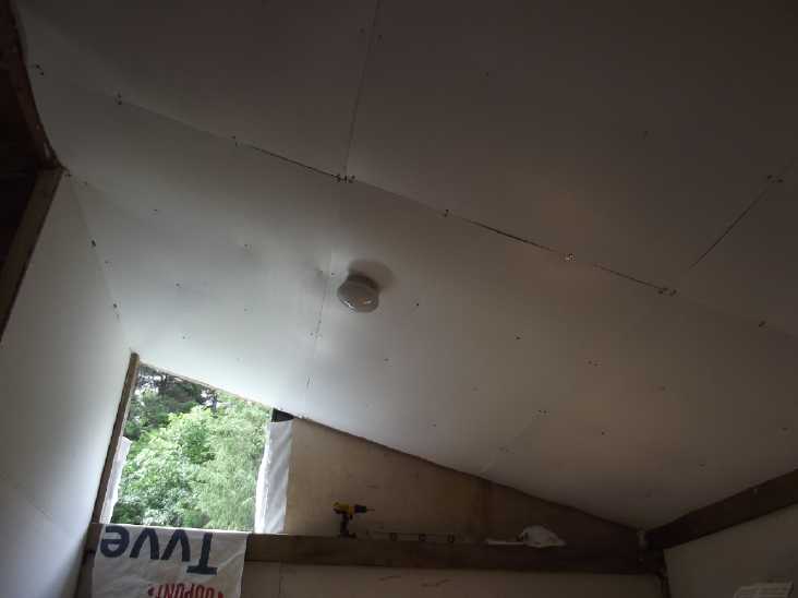 Having managed to put in thirteen fiberglass batts and
three sheets of coroplast ceiling, my endurance completely ran out and
I had to leave the last three batts and last sheet for the next morning.
[15th] I was very glad to finish the job and clean up and vacuum the
room. I went for a walk then started checking out the window frame.
I
stepped into the house just in time to hear the last ring before the
answering machine came on. It was McKenzie furniture with the "Ashley
Pillowtop 2.0" mattress, and they were just down the road! I opened the
gate and walked down to the highway to see the truck just
coming around the bend! The big mattress came in a small, very heavy
box. (14" x 14" x queen mattress width) Was that really it? All of it?
It was all vacuum packed and rolled
up to an amazingly small size. When I got it out of the box, unwrapped
the wrap and cut into the plastic bag, air hissed in and it started
expanding. Then it started to look like a real, thick, plush mattress.
"Allow
24-48 hours for full recovery." Amazing!
Owing to it being an ucky construction site I left it in
the plastic. But I brought down some old bedding and had a nap there,
and then started "camping" in it at night. I put a plastic tarp over
the whole bed during the days.
It could
almost be my imagination that my tinnitus is quieter by morning, but
it's definitely not imagination that it gets louder fairly rapidly when
I get back into "normal" electric fields. The conductive fabric
tuque/beanie actually helps a lot, but it's not the same as just being
away from electric fields. (I find this especially on the day I've
washed it and set it out to dry. The ringing is much worse after a day
without it.) Lots of older people say they have ringing in their ears
when I bring up the subject. "Oh, ya, my ears are whistling away as we
speak." The more I know and experience, the more I think 120/240 VAC
wiring should be eliminated throughout most of most dwellings.
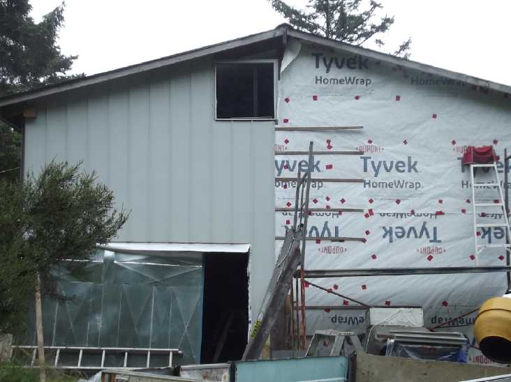 [17th] I had a double pane
window which had been two parts, one
sliding, one fixed. I had split the double pane and got it out of the
frame successfully (to clean the inside -- in spite of the sticky black
tape/goo). Now I cut the
frame down to use just the fixed part and spent the day roughing it
into
place for the bedroom window. I had to cut a small notch in the rafter
and trim the ceiling a bit,
so it was certainly the biggest window that could fit. I put the frame
in backwards so that I could put in or remove (to clean) the window
glass from inside instead of from the outside on a tall ladder.
Now the midges
("no-see-ums") would have a much harder time freely zipping in and
biting me, which makes me horribly itchy.
Only a little triangle space was left above the window to
place a vent that would open. I guess it will have to do!
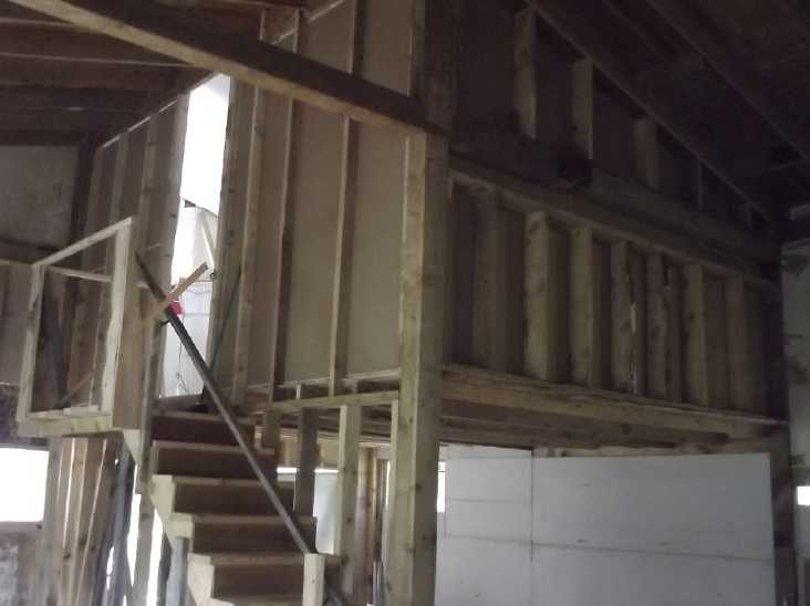 [19th] I
continued sleeping in the cabin. This gave me great incentive to finish
the last wall. I made a bizarre mistake on the framing under the center
beam: the space was 49 inches tall. Four inches had to be subtracted
from the studs for the 2 by 4's, and somewhere overnight my mind had
imprinted "39 inches". I never questioned or verified it so of course
it came out 6 inches too short. I put it up anyway. The top part with
the angles and every post a different length didn't go perfectly
either, but it ended up right.
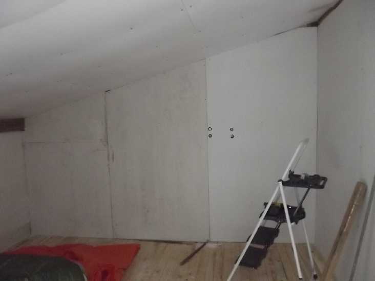 I ran the
gyproc verticly, floor to ceiling, which essentially nullified the
framing mistake. I also found I could remove the heavy beam joiner on
the bedroom side, leaving just the one on the other side and here just
bolt ends to be plastered over.
(Only one sheet of badly stored gyproc that got wet left to use up.
Yay!)
Gardening
The raspberries are
producing far more than I wanted to devote the time to pick. Still,
I've filled some margarine tubs and put them in the freezer in addition
to frequently having a good helping of them with cereal. Friends who
dropped by picked a bread bag full one day. Judging by the canes
growing for next year, I may have to get a ladder to pick them!
Corn
 By mid July
the corn was starting to grow ears! To my
surprise, the ones nearer the back were doing much better than the ones
at the front, some of which had actually died in the spring. Was not
enough light coming in near the front... or did it get colder around
the
edges in the spring? Hmm... There were pretty big cracks around the
edges. I thought they'd be fine, but the stalks in the middle and
toward the back probably
stayed warmer. Next year I'll reuse the same 'greenhouse box' [TE News #191 - scroll to bottom
of "April in Brief"] but close around the edges
better. (And maybe find something that lets more light through for the
sides?)
On August 7th I picked and cooked my first delicious cob
of corn.
Sweet Potatos
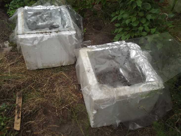 My friend Kamil said he had some sweet potatos from the
store that were starting to sprout. I've never seen them sprouting
before, so that was interesting. My brother says he grows them in his
greenhouse in Toronto. But I was sure it was too cool to grow them
here. He reminded me that I had some all-styrofoam cooler box cubes. If
I covered them with a sheet of glass and put dirt in them, the sun
would heat up the dirt and they would stay warm inside.
That sounded like a plan. So I cut a hole in the bottoms
of two and lined them with clear LDPE, and put in a few inches of old
compost, and half a tuber with some good eyes in each. I put the boxes
in the greenhouse, watered them and put a couple of broken glass or
acrylic plastic over them.
 In a week they were both sprouted! The dirt
is pretty shallow but can be deepened as they grow, and it will
hopefully fill with tubers. (Now, what about yams? I think they need it
even warmer, but might it be worth a try? I guess I should see how
these do first.)
In a couple of weeks the leaves were pressing on the glass.
Someone suggested just using soft plastic so they could lift it and
keep growing. That seemed to work well, and then I added some dirt to
each box.
 The coffee
bushes flowered and started growing new beans. I saw some nice flower
petals but when I finally went to get a picture they were gone.
I've given them bone meal, lime, nitrogen and so on, but
they could really use bigger pots. Then what when they get too tall for
inside under lights in winter?
Electricity
Storage
The
Copper Oxyhydroxide
Nickel-Manganates
Nickel Hydroxide
Nickel Oxide - Zinc
Zincate Cells
Zincate
I have already made a hugely important advance in battery
technology by creating a zinc electrode that will last 'forever'. (How
could it possibly have taken 16 years?) I think I'll call it the Zincate
electrode to distinguish it from all the "failed" (single use or short
cycle life) Zinc electrodes out there. After all, the
key is that when
discharged the zinc substance remains as a "supersaturated" zincate
solution that never turns into zinc oxide.
Nickel Manganese Oxides
[12th] After months and months with little progress I decided I was
fed up with trying to get
copper hydroxides to work - for the moment - and to try a tube
electrode with nickel-manganates again. (eg, NiMn2O4... oxidation state
varies with state of charge.) I had always tried charging these cells
up to nickel oxyhydroxide voltage (w. zinc, almost 2.0V) instead of to
manganese dioxide voltage (1.4-1.5V), and now I'm pretty sure that was
wrong. I may have been charging the manganese into soluble forms,
MnO4-, MnO4--, which would gradually migrate to the minus electrode,
reduce, and coat it with Mn(OH)2 to block the electrolyte.
In the cupboard I found a jar with a good quantity (187g)
of mix I had made in December 2022 (TE News #175), which apparently was
made with Mn substance from old dry cells using the following
percentages:
Ni(OH)2 - 29 g
Dry cell Powder ("MnO2" + CCB) - 63g
Sm2O3 - 3 g
Additional Graphite or CCB power - 5 g
(proportions of Ni to Mn are approximate)
There was no mention of acetone in #175, so I must have
discovered acetone after that. Powders simply mixed together aren't the
same as when chemicly combined. I have the impression that's another
reason the cells degraded with cycling. Acetone dissolves the oxide
powders and as it evaporates they combine them into epitaxial
co-precipitated crystalline forms. At least, this is what I think
happens - the supposition under which I'm doing it.
So that was the first step. It's amazing how crunchy
powders dissolve into a smooth paste in acetone. But it would need a
couple of days to evaporate, so I wasn't going to slap together a
NiMn2O4 electrode in an hour in the morning as I had unthinkingly
thought.
Being solid substances with no dissolving ions, probably
this electrode would work fine without osmium and SDBS. OTOH, if I used
SDBS in the separator, hopefully anything that did dissolve would stay
within the electrode anyway, and the 'forever' life of a gelled
electrode might apply.
[14th] I keep stirring it. Getting to be more of a loose powder again.
Still a faint smell of acetone... I spread some over the bottom of a
shallow container. By night the smell there was little.
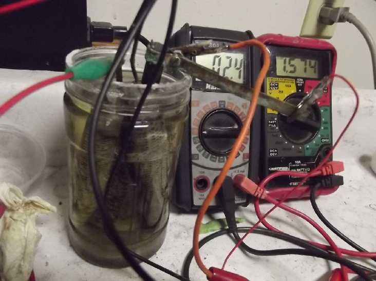 [15th] The tube with the
carbon rod weighed 30.90 grams. I added
NiMn2O4(?) powder mix and it was 42.75, so 11.85 grams of mix. Plunging
in the tapered rod and then the tapered carbon rod... and scraping some
out with a screwdriver because the rod wouldn't go in far enough... I
think I got it pretty compacted, and about 10mm below the top. I topped
it up with heat glue.
I put it in the cell and after bubbling a while it read
about 1.28V. That seemed promising. I briefly tried a couple of loads:
with 50 Ω it dropped by about 100mV and with 10 Ω, 350mV. Most of the
drop
was the NiMn2O4 side. The two old zinc tubes were pretty good. I set
the
power supply to 1.6V to charge it knowing that Mn-Zn is about 1.5V
almost regardless of pH, and that I am expecting to get a rechargeable
version of MnO2 with the mixed NiMn2O4 oxide. It started charging at
~50mA [9:35 PM PST], limited by crappy alligator clip connections and
other resistances, since the voltage only read 1.55V instead of 1.6V.
This rose toward 1.6 as the charge current dropped. (If I start
soldering connections to the cell, it gets hard to replace electrodes.)
(Note: from here, ' =
minutes, " = seconds...) In 15' of charging (which dropped to
20mA) I tried a 20 Ω load test. It started out at 1.45V O/C and dropped
to
1.1V in 1'. After 4' it was down to .977V and I stopped. This seemed
about right since it was discharging at over 50mA after such a short
charge. It recovered to 1.206V in one minute and started recharging at
60mA. Would it continue performing similarly but run longer with more
charge, or disappoint me like my copper "+" trodes? After another 30'
of charging (down to 15mA) I tried again and it ran 5', staying over
1.1V for 2'. Recovery 1.184V. Recharge started at 82mA (momentary
max.). Another test... only slightly better. ...Mañana is good
enough for me!
[16th] A test early in the mañana yielded only slightly better
results than the ones charged just half an hour. Huh? I did another run
with 50 Ω instead of 20, and it ran down to 1.000V in 20.0'. As
anticipated, it doesn't seem to be as good as the copper when that is
working well. [Later: But it also just didn't seem much good. It was
disheartening.]
How many square centimeters of interface area was there,
anyway? The last CNC cut tube had 19 rows of 18 holes, 342 holes. I
measure the drill bit as about 2.75mm (.275cm).
.275 ^sq. * π/4 = .0594 sq.cm. - per hole
.0594 * 342 = 20.3sq.cm. ... The tube was just about the same as the
50x50mm square electrodes. That is assuming of course that the holes in
the "+" tube are the greatest bottleneck, the point of least area. It's
harder to calculate for the 3D printed "minus" 'trodes but there are
two zinc "minuses" in the cell.
But this (earliest) tube had many smaller holes. Maybe 15
sq.cm? Then, it
put out 300mA into ".1Ω", which is just 20 mA/sq.cm. Of course, I
probably should try it without soduim sulfate in the electrolyte. I
had added that since it seemed to do a good job of changing copper into
CuOH. ...or does that make any significant difference?
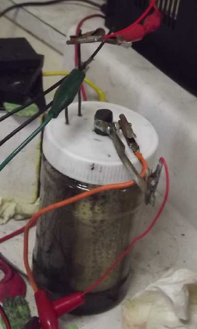 Surely I'm stumbling around in the dark. None of the
positive electrodes of whatever chemistry I try seem to have even a
fraction of the amp-hours that I think they ought to, deteriorating
performance, and (except for using cupro-nickel sheet metal), very low
current drive as well. The commercial dry cell nickel oxyhydroxide
worked better than my homemade "+" 'trodes, but not nearly as well as
it did in the original Ni-MH dry cell. What am I missing? Could
it simply be that I couldn't seem to seal the lids to keep air out?
Could a bit of air getting into the electrolyte really matter? After
all, most of the early researchers had open top beakers and jars. But
what if it affects the charging, hour after hour? There was the next
thing to try!
This jar had a plastic lid. I drilled appropriate hole in
it, filled the jar almost to the brim, poked the terminals through the
holes and screwed the lid on. Then set it on to charge again.
That done, it was much weaker. It seemed the carbon rod
just wasn't making as good a connection inside the electrode. When I
pushed on it, performance improved again. When I was done, it was about
what it was before. The idea behind tapered rods was that when pushed
in, they would compact against the electrode substance and connect
better. The flip side is if it comes out a bit, it loses connection all
around. Is there some better way to do it? (How about carbon rods with
screw threads? Well, they'd probably break putting them in.) But there
seems to be a limit beyond which pushing the rod in farther or harder
is no help. I guess at that point it's already as connected as it gets.
[17th] As I rather expected since I couldn't think of any chemical
problem except very, very gradual CO2 contamination of the KOH, the lid
on the jar seems to do nothing but keep the electrolyte from
evaporating... which anyway is a blessing. After taking out the "+"
trode and pushing the rod in pretty hard, there was no improvement over
the previous day. Once again I'm baffled as to why it doesn't perform
far better than it does.
I had the CNC machine drill
out another electrode tube. I
adjusted a setting and got 18 holes and 26 rows, 468 holes times .0594
sq.cm per hole - about 28 sq.cm.
Except maybe the drill didn't go quite deep enough and left many
'bottoms' attached. They only went back flat into the holes when
rubbed. I poked ?150? "hanging chads" with a paper clip to get them
standing up inside again and then scraped them off with a curved file.
I put in a separator paper with all including osmium.
When the tube was ready I put in 100% the old monel mix
from long ago - the baked/fried mix. It didn't work any better.
The Path of Lowest Resistance: Tried and True Nickel Oxyhydroxide
[18th] OKAY... The zincate was the vital thing. I've been unable to
improve on the other side of the cell, the positive electrode, with a
new and better chemistry.
The nickel manganates doesn't seems to work well - at
least, not if only charged to MnO2 voltage. In previous experiments at
nickel oxides voltages it had seemed to deteriorate. The copper
hydroxides/copper ions electrode seems to deteriorate and I don't see
why and haven't found a solution.
There is almost surely some way or multiple ways to make
either and both of these things work, but
for myself, I think it's time to give up on them. I've simply had
enough of failures.
At this point, I think there are two choices:
1. Delve into the uncharted realms of zinc-air cells. This probably has
even more hurdles and unknowables than what I've already been doing. I
think I'll pass. Hopefully the U of Waterloo is still carrying on their
zinc-air research and I've written to them with my good 'everlasting
zinc' suggestions.
2. Take the path of least resistance on the positive electrode... Tried
and Tested, well known and long used Nickel Oxyhydroxide, NiOOH. (AKA
nickel hydroxide. Oxyhydroxide is the charged form.) A nickel-zincate
cell that lasts "forever", or at least for many thousands of cycles,
would be a fabulous battery. It would be notably lighter, cheaper,
higher voltage and higher energy than nickel-metal hydride, and surely
less costly and safer than lithium types. The PVC plastic pipes with
holes should be able to sufficiently compact the electrode substance
(NiOOH needs to be held under quite strong pressure for the substances
to conduct well). Now... can I make ones that work? I've
done reasonably well with nickel electrode substance from dry cells...
and I actually still have quite a few Ni-MH "D" cells to recycle. Plus
I have plenty of nickel hydroxide and other chemicals used for that
chemistry.
Going from valence 2 [nickel hydroxide] to 3 [nickel
oxyhydroxide] moves one electron per nickel atom for a theoretical
figure of 289 mAH/g. The oldest nickel oxyhydroxide mixes as used by
Edison in the early 1900s probably yielded an actual, practical figure
of around 90. It was hard to attain a total nickel valence above
(?)2.8, and if the valence falls below about 2.2, the conductivity
becomes very poor, so the actual available valence change between
charged and discharged was (theoreticly) 60% of the theoretical. In the
Ovonics patent
with various trace additives they claimed to be attaining a mixed
valence above 3, with some Ni centers being valence 4, thus going from
valence 2.2 [fully discharged] to about 3.2 [fully charged] and a
figure of around 200 mAH/g. There's a lot more to the chemistry and
crystalogy(?) in all this, but the result is that 'modern' nickel
electrodes are now twice as good as they used to be.
It occurs to me that Chinese manufacturers probably
wouldn't do much research and would simply copy whatever existing
chemical mix was best - probably the Ovonics mix. To make dry cells
they would probably
have just shrugged about the patents that prevented anyone in the USA
and Europe from making more Ni-MH EV batteries (which of course has led
to
the worldwide adoption of lithium battery types instead). And anyway
Ovshinsky's
key patents expired in 2014.
I added some 'ovonics' mix into the center of the dry cell
NiOOH tube
(from last month) and stuck a new rod into it, and glued the top. It
didn't want to charge at all fast. But even without much charging, on
discharge it would - momentarily - put out 150mA at 1.6V into a 10 ohm
load. (Then charge pretty fast to make up what it had just lost, then
go back to a few mA. All presumably because the zinc side was already
charged and had no OH-'es to supply to the nickel.) Hopefully discharge
would stay up there with the fabled 100 or 1000 hours of charging.
Then let's see if I can actually make one 'from scratch'?
I had a little of my 'ovonics'+graphite+Sm2O3 mix (acetoned) left;
maybe not enough to fill a tube. I emptied the short tube of copper
substance and refilled it with the 'ovonics'. Pipe 14.40g +carbon rod
9.30g = 23.70g. Filled it was 32.10g, 8.4g of NiOOH mix. [Wait, I
actually used NiO, not Ni(OH)2! - more on that further down.] Less than
an
amp-hour I suppose? Well, I can only try out one at a time, so this one
will have to wait.
[19th] Wait... the short one fits into the square cell with the lid on,
which has a square zinc 'trode in it. Anyway, the large tube with the
"D" cell stuff in it plus a bit of 'ovonics' mix around the carbon rod
put out good current but it didn't run long. [It got better]
I started testing by running it down to 1.400 volts with a
50 ohm load. This occurred in ~4'30" a couple of times, then with a few
more hours of charging, in the afternoon it went for 6'. It seems to be
improving instead of getting weaker like so many (all?) of my other "+"
trodes. By another 94 hours (or is it 994 hours?) it should acquire a
good charge. If only it would charge faster! But it charged quickly
enough after driving a load, then went back to vey low currents,
doubtless as the zinc side became fully charged again. A couple of
hours later: 7'30".
I remember that once I tried "D" cell nickel substance and
got good results with 20% KOH and 20% KCl electrolyte. Now I'm using 5%
KOH and 10% KCl. Might it be worth adding a few percent more nasty KOH?
The cell is around 400cc so 8 grams should add 2%, making it 7%. I did
that. Short circuit had been around 400mA. Now I got figures of
330mA-440mA that seemed to depend mainly on the relative positions of
the electrode tubes in the jar (and maybe the alligator clip
connections) rather than the concentration of KOH. (Checking with an
ampmeter straight across the terminals instead of through all the
alligator clips, switch, wiring & .1Ω resistor it read over 650mA.
Good enough - it's a real battery!)
Best NiOOH Mix?
I re-read some of the Ovonics European patent for nickel
hydroxide electrode. (EP 1 672 724 A2 . If anyone thinks some of
my chemie stuff is involved and technical, this document seems
well written with good explanations, but it's a really heavy
read. And in some places even they say "We think it works like
this...") There was something I had missed before: the particles of
nickel [oxy]hydroxide were coated with cobalt oxyhydroxide.
This made for good electron conduction between particles without other
additives such as graphite - and somehow still allowed proton transfer
to the electrolyte. Also, they stressed small quantities of
'dopant' metallic atoms made for improved proton conductivity
within crystallite particles - from the interior to the edges where the
electrolyte is. (You don't get NiOHOH <=> NiOOH without that H+,
and its associated e-, moving around somewhere!)
These features, and perhaps even more the technology
employed to achieve
them, is very impressive. However I'm going to venture a guess that my
technique of simply dissolving the final compounds (not precursor
compounds) in acetone and letting them form into epitaxial crystals
that contain all of the very same substances Ovonics ends up with, will
work just as well. Most of the 'dopants' will be the same. The cobalt
will go in as a 'dopant' instead of being a skin around the particle.
That should improve electron and proton conductivity through
each particle. It might still want a bit of graphite to improve
electron conductivity between particles, but with the conductive cobalt
in the particle edge here and there, it should be quite a small
percentage of lightweight graphite.
Anyway, that's my theory. Making working positive
electrodes hasn't been my strong suit so far.
Nickel Oxide?
Another thought is that nickel oxide (NiO) has been
identified (as seen briefly in a web search) as a good potential
battery substance - for lithium
cells. Might it work better than hydroxide (Ni(OH)2) in a moderately
alkaline nickel-zinc cell? Would that
reaction go to oxyhydroxide on charge and then back to oxide on
discharge?:
NiO + OH- <=> NiOOH + e- ? or would it simply convert to
hydroxide on discharge?:
NiOOH + H2O + e- => NiOHOH + OH-
or would it not convert at all?:
2 NiO + 2 OH- <=> Ni2O3 + H2O + 2 e- ?
I had thought it would just convert to hydroxide, but now
as far as I can find, copper, the next element over, doesn't ever seem
to convert from oxide to hydroxide. Why have I never heard of nickel
oxide as an alkaline battery substance? I would think this would be
worth trying. Perhaps it's because there is no convenient process for
converting the usual nickel sulfate precursor into nickel oxide instead
of into the hydroxide?
But the oxide is denser than the hydroxide also with higher percentage
of
nickel per gram:
NiO : 58.7+16=74.7
Ni(OH)2: 58.7+34=92.7
289 mAH/g * 92.7/74.7 = 359 mAH/g. (per single valence change) If it
works per the last reaction
(NiO <=> Ni2O3) it would pack a lot more punch than the
hydroxide. And it might sidestep the whole question of beta versus
alpha and gamma and swelling/shrinking of the different forms.
I suspect it's all a matter of crystallography how it
actually works. If it starts as a nickel oxide crystalline substance,
perhaps it charges to a different crystalline form of oxyhydroxide than
if it starts as hydroxide, or perhaps to a form of nickel "peroxide"
instead.
Definitely worth a try - a substantial improvement if it
works!
[20th] Another night of charging. Charging current is up to 11mA
instead of unit mA. (Improving - or leakage between trodes?) 50 Ω test
down to 1.4V ran for 9'30". That's still improving.
Info says NiO is green. When I made it by roasting
Ni(OH)2, it was black. Maybe I made Ni2O3, or a nonstoichiometric mix
of NiO:Ni2O3? This time I decided to buy some. Best choice seemed to be
an AliExpress store, ~130$C for a kilogram of "high purity nickel oxide
powder". The one review said it was very fine - 5 stars. (Sigma
Alderich wanted 900$C for 500g. Pottery supplies saying "nickel oxide"
actually had "mixed" nickel compounds for glazes, oxide/hydroxide plus
carbonate - but that they "will turn into NiO when fired". That sounded
the same as making my own but starting with a supply of dubious purity.)
A 50 Ω load test ran for 10 minutes. With 20 Ω it only ran
3' down to 1.4V. OTOH it was putting out 70mA instead of 30.
I can't find anything on line about using NiO for alkaline
cells. Oh no, am I breaking into new, untried territory again?!?
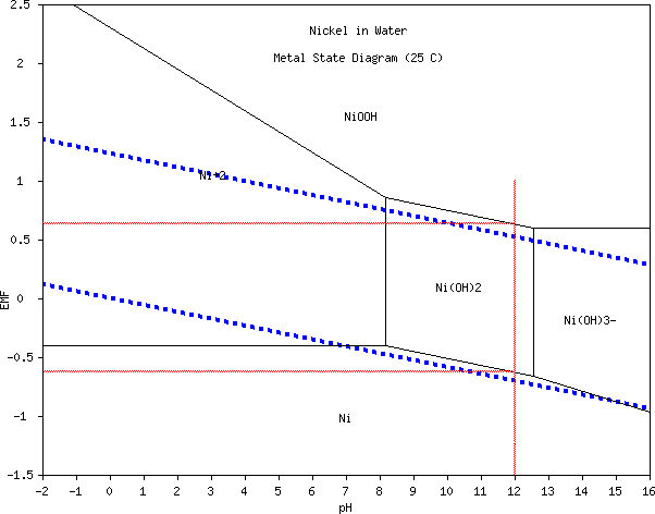 This nickel pourbaix
diagram suggests
that Ni(OH)3- is formed at pH 13-14. This isn't mentioned in battery
literature. One expects it would saturate at very, very low
concentration. Even
so, it could limit the 'forever' life of the cell if not contained
within the
electrode. So even with nickel, my positives are going to get the full
ion blocking treatments of SDBS in the separator and osmium doping.
Nor is NiO nor Ni2O3 mentioned anywhere, and I
havent found anything about convertibility between nickel oxides and
hydroxides.
[21st] Charge current is over 20mA. When
turned off, the cell drops quickly to 1.90V instead of drifting slowly
down through 1.95V. (Is there a low resistance path somewhere? But I
can move the individual electrodes around, so they can't stay shorted
and if there is, it's in the electrolyte itself. Hmm, it keeps dropping
if left idle, below 1.7V.) With a 50 Ω load it drops immediately below
1.8V spending no time in the 1.8xx region (not that it stayed long
there before). But it ran 11' total down to 1.4V. (Originally I thought
I should be
running it down to 1.3V. 1.2V nominal cells are usually tested down to
.9V, so a 1.6V should go at least down to 1.3V? But in fact the voltage
starts dropping really fast below about 1.46V.) Recharge current after
each
test has been steadily rising with initial peak currents starting
around 60-70mA. It's now over 120mA.
Replacing the electrolyte had no effect. Instead, what
seemed to be happening was that the cupro-nickel clamp around the
carbon rod was resting on the jar cap, and electrolyte had seeped up
and made contact. This had the effect of trying to oxidize the clamp,
at a lower voltage than nickel and so discharging the nickel electrode.
Yikes! I took it apart and reset the clamp, then put a little plastic
disk under the clamp so it was above the jar lid.
[22nd] Nope, that wasn't it either! A load test didn't run long. I
fiddled with the connections. One of the zinc trodes was disconnected
and the voltage went up. Was one of them somehow bad? Then I noticed a
bit of something - powdery, and no doubt damp - on top of the lid,
which seemed to run between one of the zinc "-" terminals and the
carbon "+" rod. I wiped it off. That seemed to solve the problem -
for few moments! Then it occurred to me that I had filled the
jar, and when the electrodes were put in it rose right to the brim.
Another turn of the lid, if there had been one, would probably have
brought it squishing out the edges. That meant it was above the top of
the electrodes. If the glue there wasn't perfect or maybe if the
separator papers didn't come to the top, that made a path for whatever
(ions?) to come out of the electrode. I hadn't intended them to be
totally immersed. I poured out about 30cc so I could see the level line
inside.
With just one zinc connected, after another hour of
recharging a 50 Ω load test ran all but 15'. Still not long. Later I
came back, thought it wasn't quite right so I moved the electrodes
around a bit, and this time it took nearly 7-8 minutes to drop under
1.7V. At 20' it was still 1.622V, putting out 30mA. This was seriously
cutting into my nap time! What did I finally do right on
something I was getting pretty disappointed with?
A 50 Ω load test later ran about 40'. Into the evening,
there were definitely bad connections which had doubtless been messing
with the results all along. I took the lid off the jar, and I sanded
and filed the clamp connecting the carbon rod externally. After
considerable charging (with higher currents!) it looked stronger than
ever and like a 50 Ω test would run much longer than I wanted to sit
around for. A 20 Ω test with (both zincs connected) ran 6'30" to 1.4V.
Momentary short circuit current was as high as 800+mA.
[23rd] My chief problems seemed to boil down to two: poor connections
and one of the zinc tubes was poor. The zinc tube (if not both of them)
was probably made back last fall before I had everything completely
worked out. It worked better with that one removed. There was virtually
no extra voltage drop under load, saying that it's limited almost
entirely by the nickel side. (Theory said it would take several nickel
tubes to balance one zinc tube anyway.)
The worst of the recurring poor connections was that
between the carbon rod and its clamp. It doesn't seem one can use
anything but carbon/graphite as a current collector inside positive
electrodes unless they are full caustic pH 14, in which case nickel
forms a thin, solid skin of NiOOH that protects the underlying metal.
But even that doesn't seem to last 'forever' - maybe some years, a
couple of decades or even a few. Carbon seems to be the best (if not
the only) choice. The cupro-nickel or monel I was trying at lower pH'es
doesn't seem to work as well as I had thought for a while. It is
however much better than copper or nickel alone. Perhaps someone will
figure out an alloy that works 'perfectly' some day.
Gold for Connections?
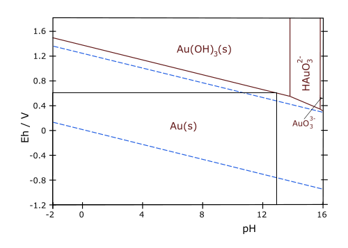 Or!... come to think of it... gold! The alkaline reaction voltage of
nickel to oxyhydroxide is around .5V, gold to gold hydroxide is about
.6V. It doesn't seem like a very big margin of safety, but if it works
and doesn't degrade it would certainly provide high current capacity.
Or even if it oxidizes, if an impenetrable Au(OH)3 layer will form on
the surface at pH 12-13, that would protect it while charging. When
charging stopped that surface would discharge back to Au metal - at
least, as soon as there was a load. (Wait, where was Jungner when he
was testing all the metals and found that "only nickel" didn't oxidize
away? Did he try gold? But he was doing pH 14, and there can still be a
difference between pH12-13 and pH 14.)
Of course if I end up picking a lower voltage positive
electrode (NiMn2O4 [same as MnO2] or CuO), gold would safely remain in
solid metallic form. (Platinum and all[?] other metals would oxidize.)
Gold is a bit pricey, but gold plating might work. (It
hasn't worked for me so far, but then I wasn't very happy with the
results I
got from the gold plating solution I bought the one time I tried it.)
For the clamp connection to the rod, gold is the one metal that springs
to mind. Gold plating. Surely I can at least do a tiny area of good
plating for a clamp.
And while I'm at it, maybe I could gold plate a few of
those ever-troublesome alligator clip test leeds. (All non-soldered,
non-crimped or not-screwed-down-solidly connections seem to be
troublesome. Even the contacts inside the switch, and it's the second
switch I've used.)
[25th] To continue this theme, my chief concern with electroplating is
that if the metal underneath is susceptible, anywhere there's the
slightest gap in the plating - whether made during the plating process
or from stresses afterward - the metal will be eaten away and
eventually cause failure. From all I've heard, eventual corrosion
appears to have been the fate of most long life nickel-iron flooded
cells.
So I wondered if gold could be electroplated over
graphite/carbon. Then it could contribute its conductivity and if there
were any gaps, nothing would happen to the graphite. The answer is yes,
and where I read it mentioned carbon fiber. Somehow I had forgotten
about carbon fiber. It would be a good alternative to a carbon rod, or
an electrode addition, allowing connections to be dispersed through the
electrode substance. BTW Technicly "carbon" of course is the
element and it may have forms such as graphite, CCB, diamond, amorphous
carbon and charcoal. But "carbon" seems to be used almost
interchangeably with "graphite" in solid "graphitic" forms. I'm unclear
about the difference between "carbon rod" or "carbon fiber" and
"graphite rod" or "graphite fiber". It would seem that graphite is pure
carbon where "carbon" might have epoxy in it. or not. (But how could
"carbon fiber" be anything but graphite?) Graphite fiber would surely
be an excellent current collector - or conductivity additive (something
I've done before). And still better if gold plated.
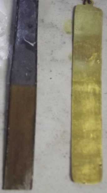 I
found my gold plating solution (from 2019) and tried
plating a small piece of graphite foil. It worked.
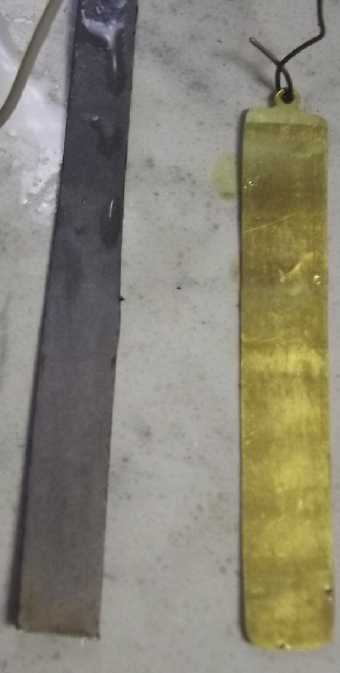 I rubbed one face to
shine it up - and most of the gold rubbed off! The yellow color was
pretty much gone and it only remained in the recessed spaces. I guess
being able to electroplate it doesn't stop graphite from being slippery
and
greasy! There's probably enough bits left to improve conductivity, but
it's disappointing that it comes off so easily. I can't imagine there
being much left if a graphite rod is jammed into an electrode and
twisted to compact the powders... and to get good connection.
But for electrode production, I can imagine gold plating
carbon fibers and having something like an "iris" tube where the nickel
oxide mix and the fibers are laid in with the fibers oriented top to
bottom sticking out the top, and then it's squeezed down to the correct
diameter. A closed-end gold plated metal tube (like a very small bullet
casing?) presses the fibers together at the top to form a terminal.
Hmm... or they are glued together into a terminal. A prepared separator
paper is wrapped around, and then it is inserted into a holey tube and
a is top pressed on.
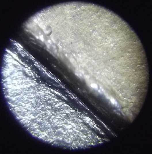
 Left: gold plated versus unplated
Right: gold plating wiped (much less left) & unplated
Next: Improving Performance
At this point I have a working nickel-zincate cell. At
long last I'm through finding two basic battery chemies (a plus and a
minus). But the "plus" electrodes, even the nickel, surely aren't
performing even colse to capacity so next I'll be into performance
improvements. Now I can see there's lots of further experimentation and
development work to be done on that - ug! But the resulting batteries
are bound to be fantastic!
Continuing Tests
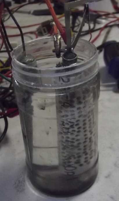 [Back to 23rd] When
connections &c are good, charging day after day
seems to be improving it. With a 50 Ω test in the afternoon, in the
1.75X range, the drop rate was down to about 8 mV/minute, way under
half what it had been a couple of days previous. Then it slowed down.
It finally hit 1.700V after 22'. 40' - 1.661V. I noticed current was a
bit low for the voltage - not by much, maybe 6-10%. I fiddled with an
alligator clip and flipped the switch a couple of times. Yup, that was
it. 27mA went to 29. 1.6V, 50Ω = you'd expect 32mA, but it's never
quite as high as expected. 50' - 1.642V. So it's only dropping about
2mV/minute. Great! This is cutting into my nap time again!
It's good that it's running more the sort of lengths of
time one might expect. Nickel hydroxide is certainly a breath of fresh
air after all the frustrations with promising but not quite delivering
copper hydroxide! 60' - 1.632V: now just 1mV/minute drop rate. If this
rate doesn't change it should run for 232 more minutes before hitting
1.400V. (No doubt it will change, but there a ballpark duration -
adding in the first hour, that's 5 hours. Much longer than any previous
test, probably owing to removal of the 'bad' zinc tube as well as - for
the moment - pretty good connections.) 90' - 1.581V [50mV in 30' = 1.67
mV/'] 130' - 1.255V oops. (I thought I could go away half an hour!
Obviously must have started dropping off quickly at some point.)
In the evening I ran a 20 Ω load test, which
started in the 1.7XX V range and was soon down into 1.6XX, starting
around 71mA. It stayed above 1.6V for about 10'. 15': 1.58+V, 64mA;
20': 1.558V, 64mA; 30': 1.510V, 61mA. It ran for 39', rapidly dropping
through 1.4XX V, especially below 1.45X V. It seemed like very good
performance, especially compared to the previous 6'30".
 A footnote is
that after changing the electrolyte, and
with trodes that are no longer brand new, there's still black stuff
accumulating on the bottom of the jar. Either a tube is leaking or
substance is dissolving out and then solidifying and precipitating out.
I see greenish (& black) nickel oxide or hydroxide in the holes in
the pipe wall. Probably it's outside the separator sheet. Likely
Ni(OH)3- ions, spontaneously converting to NiOOH(black)+H2O? Hopefully
if I put osmium dopant on the inside surface of the sheet it'll prevent
the penetration and the conversion. Hopefully. (The zinc also has a bit
of black around the holes, but I don't think it's emitting
anything. If it is, well, it's not the latest design.)
[25th] Another 20 Ω load test,
this time running 12' (even) to
1.600V instead of 10'. It ran throughout with slightly higher voltages
(& currents) but still pooped out at about the 40' mark.
[26th] I left it off charge overnight. It fell from ~1.9V to 1.78V.
Then I ran a load test. It dropped through 1.600V in about 3' instead
of 10+. It ran for 35' instead of 40, so it had lost around 3/8 of its
charge in around 9 hours. That certainly needs improvement but it's
better than a lot of my cells that lost most or all their charge
overnight. The "bad" zinc tube had caused very high self discharge.
Perhaps my newest ones are okay?
Since the top was off the jar I stuck in a reference
electrode and verified during the test that it was the nickel side
losing voltage while the zinc stayed pretty constant and obviously
would have run for hours. (It would seem a graphite reference electrode
is about zero volts, since the measurements of zinc as -1.32 V and
nickel oxy. as +.52 (charged over theoretical), when the theoretical
values are -1.28 and +.48. The one with gold plating seemed to be
~~80mV more positive, giving a larger value for the zinc and smaller
for the nickel (eg, -1.33, +.43.)
The Nickel Oxide Trode
I decided to try the other one, with my 'Ovonics'
completely 'homemade' nickel oxide mix (TE News #186 - or as it was
there
calculated, next...) instead of nickel hydroxide coming from
dry cells.
NiO ----- 74.7 * .95 = 70.95 g
Co2O3 - 82.9 * .03 = 2.50 g
CaO ---- 56.1 * .01 = .55 g
MgO ---- 40.3 * .005 = .20 g
ZnO ---- 81.4 * .005 = .40 g
--------
100g,
100%
I thought when I made it that the nickel content would
just turn into hydroxide anyway (NiO => Ni(OH)2, in a more compacted
way), so the idea that it may be better will get a bit of a test. (Too
bad the rod won't come out easily. I could try gold plating it!)
Current started out at 0 mA and I thought some connection
was wrong. Then it rose to 1. then 2, then 3. There it stayed, probably
again because the zinc was already charged and had no OH-'es to
contribute? But it was charging, however gradually. Once again, it
looks like days, not hours, will tell.
In the evening I got tired of waiting. I took the
electrode from the cell and put it in a small bottle with a teaspoon of
bleach to help oxidize the nickel from NiO oxide to (best guess) Ni2O3,
or to NiOOH - the charged form. I let it sit for 5' then filled the jar
with water and rinsed it for 5' (hmm, maybe 10'+).
I put it back in the cell. It seemed to have no charge
remaining, but the initial charging current seemed higher. First run
times were [even] shorter. I got the impression that the bleaching had
accomplished nothing. Momentary max short circuit current was still
~~250mA.
[27th] First 50 Ω load test of the morning ran for 50" (seconds!)
instead of 30. It's an improvement, but it doesn't look like it's ever
going to perform well. I'll chalk it up to my homemade nickel oxide
being black instead of green and wait for the real thing, now on order.
Actually, maybe I'll try opening the tube, see if I can squeeze in any
more powder to make it more compacted, gold plate the terminal rod, and
try it again.
[28th] I did that and it ran for 1'15" instead of just a minute. It
would seem I'm on the right track, but that it needs to be compacted to
another whole level. That would mean opening the top of the tube and
pressing the powder in with a press. (Then drilling the center out so I
can put a rod back in.) How much more can it be packed down from its
already "pretty packed" height?
I pulled out the rod and filled the hole with loose
powder. I took the tube out to the hydraulic press and using a 1/2"
shaft as a plunger, compacted it quite a bit further. After some
fiddling around and drilling, I pushed the tapered rod back in. But it
didn't go in so far. I used the press to push it in notably further
(maybe to the bottom of the tube). I didn't use a lot of force for fear
of cracking the rod, but it was notably harder than I could push it in
by hand.
Back in the cell, the charge started around 80mA instead
of around 40. So far so good! When charged, it drifted down from 1.999V
through 1.95V more slowly, where before it would soon be 1.90. With the
50 Ω load it went through the 1.7XX V range (rapidly) instead of
dropping right to 1.6XX. There the good news ended because it ran down
to 1.400 V just as fast and dropped down under 5 mA charge current just
as fast.
???
[30th] No improvement at all - still discharges in less than 90". In Inside
the
Nickel
Metal
Hydride
Battery by John Kopera (2004) he described
an unwanted byproduct of charging as being K(NiO2)3
[soluble], in which the valence state of the nickel somehow averages
+3.67. Perhaps starting with NiO it charges to this state, which would
be a soluble ion, instead of to NiOOH? IF so, perhaps we can make it a
useful product instead of a problem, again with SDBS to keep within the
electrode and osmium catalyst to keep it in solution. If it works,
charging to nickel valence +3.67 instead of just +3 would move 5
electrons per 3 nickel atoms, instead of just 3, giving us a
theoretical 289 * 5/3 = 481 mAH/g. Actually, that would be for starting
with Ni(OH)2. That would have to be combined with the calculation under
"Nickel Oxides?" from the 19th, above, and it should be even higher
than that. Half an amp-hour per gram, combined with nickel's high "+"
voltage, would be really impressive.
And if, like the zincate ions (only
opposite), dissolving bits expose more reactant as charge proceeds,
more of the electrode's substance will be utilized, getting it closer
to the theoretical value.
I've done it all in this electrode except the osmium
doping. There's only one way to see if that was the vital missing step.
I'll take this one apart and redo it since I have no more of the
"Ovonics" mix with nickel oxide instead of hydroxide.
I put the stem of the rod in a vise and to my relief
managed to get it out without snapping it. (That would have made it
really hard to get the substance out.) I got the electrode substance
out, but as usual with a disassembly (and especially when the powder
mix was so strongly compacted into the tube), minute bits of separator
paper were all through it. I pulled out many bits with tweezers, but it
doesn't make the mix any more conductive! I found one last toluened,
PP'ed sheet of separator paper. I cut it to fit, soaked it in SDBS for
an hour, then dried it. I painted it with osmium doped acetaldehyde,
but it might be a bit thin. I discovered that I was out of osmium
powder. I ordered some more (in May?) But I keep getting emails saying
it's being delayed, now until September. (Maybe by Christmas?) Then I
put the trode together the same way it was before. It took about 13
grams of the NiO mix.
While it was apart I reconnected the other cell. It was
still holding 1.72 volts. No doubt I should have done a load test to
really see how much charge it had left. But I just put it on
charge. It charged for around 3 hours at over 30mA. Then I decided to
do a 50 Ω load test and see how much of that was actually charge being
retained in the cell. It started out around 1.8V delivering 35mA. At
100' it was still putting out 1.565V and 30mA. (By now my new NiO trode
was ready. Now it would have to wait for the test to end!) After 2
hours it was at ~1.515V, 29mA. 135': 1.465V, 28mA. It dropped through
1.400 V in 153', sourcing 27mA. (Total about 90mAH. Okay, not huge.) In
half an hour it only recovered to 1.55(?)V. But I wanted to try the new
electrode!
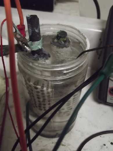 On a whim I
put it into the same jar cell, simply
disconnecting the Ni(OH)2 electrode and subbing the new NiO one. I left
it a few minutes to soak. After the load test, the zinc couldn't be
fully charged, so it couldn't be blamed if charging current was low.
Sure enough, charging current soon dropped to 9mA anyway, and a quick
load test was quick because it only ran for 50".
But in spite of charging at just 5-6mA, it seemed to
improve over the hours, where previously it was stuck at about 1'25".
Now... 50". 1'20". and through the evening, 2'10". 2'40". 3'10". It
would have to keep improving for a long time - or the rate of
improvement would have to rise a lot - before it could be considered a
good electrode. But it just might do it!
[31st] Charging current is up to 9mA from 5 or 6. Yet the voltage drop
soon after removing charge seems to be less. Theory says that nickel
valence 2 is a low conductance semiconductor whereas valence 3 is a
much better conductor, so increasing charge current as it starts to
charge should be the result. A 50 Ω load test in the morning ran for
7'10". Recharge started around 140mA instead of 40, 60 or 70. Short
circuit current, which had been consistently 250mA before the osmiumed
paper, was over 600. This shorter tube probably has half the holes at
best, so that's probably the equivalent of 1.2 amps from the larger
tube - great! The osmium seems to have made all the difference!
Early PM: 8'00". Later: same. Later: same. Has it got
"stuck" at 8' the way it did at under 2' before?
[August 1st] I got to it at noon, so it had about 12 hours charging.
This time it ran for 9'. Is it working, or another failure? Painfully
slow improvement and will it continue? Why does it seem less than 1% of
the intended amp-hours (as usual) is available. I decided to try
running higher currents to see if that might induce any more substance
to come "on line" as it were, and I did some discharges at 10 Ω, down
to 1.100 V. (Below 1.1 V the rate of voltage drop, already fast,
doubled.) These ran for less than 2'30".
MORE Compaction!
[Aug 3rd] Seems to be stuck. Great current drive, not 1% of the
amp-hours it ought to have. I keep running up against this wall with my
positive electrodes no matter what chemistry I try. Only the ones with
material coming from dry cells work - and even then only to a greater
degree with nothing like the expected amp-hours. What am I missing?
Maybe I'll try compacting one even harder - a couple of tons of force
in a metal tube so there's hard "chunks" in the mix before I put it
into a cell. That's probably the key difference with dry cell material:
I'm using seemingly pretty hard chunks that I don't grind to powder.
The more I thought about it, the more sure I was that that
was the problem with all of them. I had heard copper and nickel oxides
both needed tons of pressure, not just to be basicly munched together.
The Ovonics patent mentioned around 3 grams per cc of their compacted
hydroxide mix. I may have had half that, if, which would mean I should
be able to crunch the stuff way farther down.
How did I get here? 3 or 4 years ago I was testing with
flat electrodes and pressing down with my body weight. The currents
went up up to a certain point of pressure, beyond which they didn't
increase. Despite having read about the high pressures required for
Ni(OH)2 and CuO, I had concluded that that was sufficient
pressure/compaction - and have ever since been operating on that
assumption. But probably it was enough that the current became limited
by the interface area and wouldn't rise further, but much or most of
the substance still wasn't in good (any?) electronic contact through to
the current collector, so available amp-hours was very low. At least,
this fits the symptoms. I started making round "porous" plastic
electrode tubes last year instead of flat, to hold some pressure so the
material couldn't expand, but it couldn't be compacted enough in a
plastic tube to start with.
 I
made a jig with some stainless steel pipes and a bolt. I intended to
press to 5 tons and get a tall "donut"/toroid. It didn't go well.
Watching the gauge, after 3 tons the pressure stopped going up. Finally
I looked down to see that the pipe had bent! The pipes were also
mushrooming at the ends a bit. Furthermore, when everything was
corrected and I tried just two tons, the "plug" stuck in the pipe. Even
with the end unsupported,supposedly to simply pop out, the material
just kept compacting. Ug! (Maybe try half as much material?)
I
made a jig with some stainless steel pipes and a bolt. I intended to
press to 5 tons and get a tall "donut"/toroid. It didn't go well.
Watching the gauge, after 3 tons the pressure stopped going up. Finally
I looked down to see that the pipe had bent! The pipes were also
mushrooming at the ends a bit. Furthermore, when everything was
corrected and I tried just two tons, the "plug" stuck in the pipe. Even
with the end unsupported,supposedly to simply pop out, the material
just kept compacting. Ug! (Maybe try half as much material?)
Giving up on that, I
finally took the last PVC tube made with the long rod and started
compacting the material in it further, inserting different diameter
bolts and pressing them in - not hard - with the press. Finally I
pressed the rod in harder than I could by hand.
I thought this tube had nickel manganates. Now I see in my
quick experiments I didn't take any pictures of any of three tubes and
now am not sure whether it was the one of copper, the one of
nickel-manganates material, or the one of the really old mix. Oh great,
now I'm sure it isn't half as compacted as I wanted and I don't even
know what it is! I decided to charge it at 1.5V as if it was copper. If
it was the other, it wouldn't charge much.
[August 4th] The behaviour said it was copper. And it didn't work any
better. I put it aside. I took the short tube with the nickel oxides
out to the shop, twisted the rod out, dug out the heat glue, and
started pressing the powder in better. If it didn't break the paper or
the tube, or the rod, I was at least going to compact it better than it
was and see if it performed, at least, better than it had. When I had
finished pressing it down with various bolts of different diameters, I
put the rod back in, again pressing it in with the press. The rod
cracked, but it sheered verticly from the top. There was still enough
to connect to. Unfortunately it didn't go in as far in the denser
material - there was probably 1/2 inch at the bottom now rather distant
from it. That may negate some gains. The NiO mix was down to about 1/2
the tube instead of 4/5. I didn't think the heat glue would fill that
far in and, lacking more NiO mix, I stuffed in some NiMn2O4 powder -
not very compacted, but just to fill the space. Then heat glue, and
back into the cell. Again charge started at 0 mA. This time I was less
surprised and I just waited for it to start coming up. In half an hour
it was 8-9mA.
[August 5th] I decided to try pressing the graphite rod in farther by
removing some material within, but I broke it trying to get it out.
That was it for that trode! What next? I didn't have any more nickel
oxide mix. Hopefully the new nickel oxide will arrive soon.
[August 6th] Back to the compacting jig, I turned a bolt to go into the
outer tube to make a solid "plug" of electrode material. I pressed it
to 2 tons. It worked great. Then I tried to make another one but drill
a 1/4" hole through it before removing it from the tube. When I pushed
it out of the tube it broke apart. Rats!
 I
had improved the "exit hole" in the plate to hold the pipe centered
properly and I went back to the previous arrangement. Again I used 2
tons, and given the small area being pressed, that's probably enough.
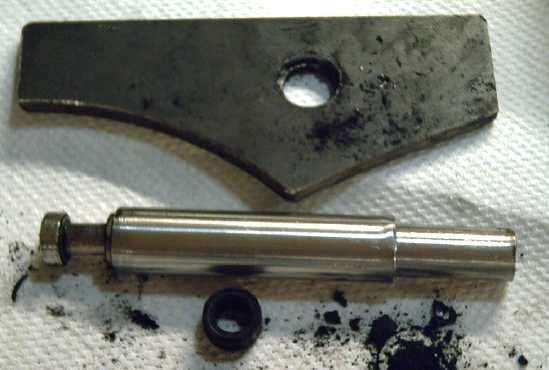 I extruded a
nice donut and to my surprise it slid off the inner bolt easily, so it
had a hole for a carbon rod. I tried again using a bigger spoonful of
powder to make a longer one. This one worked but had a lot of loose
powder around it. If the original scoop of powder extended past the
inner bolt, that would happen. Also the tube wasn't quite small enough
inside, so there was a bit of a gap around the bolt. I'd like to do
something about that. Enough for today!
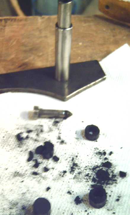 Successes! The solid "plug" lower
left, two
usable donuts on right,
crumbled tall donut mid left.
[August 8th] Production turned out to be rather exacting: less than 2
tons pressure the donut would be crumbly and fall apart. More than 2
tons the narrower stainless steel pipe would start to bend. More than
about a level tiny spoonful of powder (1.5g) and the donut would be
crumbly and fall apart. Also it starts getting very hard to press it
out of the pipe if too much powder is put in, which again could lead to
bent pipes. I had to make 10 short donuts (7-9mm tall - a couple were
10mm) to get enough for a 4 inch electrode tube, instead of 3 or 4 tall
ones.
 Enough short NiMn2O4 donuts for a
4 inch
electrode tube, strung on on a 5/16 inch carbon rod.
Let's see: 8mm long, 13.8mm OD, 8mm ID
8 x (13.8mm^2 * π /4) - (8mm^2 * π/4) = 794.4
cubic mm = .794 cc.
1.5g / .794cc = ~1.9 g/cc.
If it was nickel hydroxide, that's not especially well
compacted (should be somewhat over 2 g/cc). Since it's nickel-manganese
oxide, we don't really know what it's "supposed" to be. But it's
probably much better than I was doing before and sounds like it's in
the right ballpark. The next challenges are (a) to get the string of
beads into an electrode tube with paper in it without crumbling them or
shredding the paper, and (b) hoping they make good contact with the
5/16" carbon rod and that they don't find room to swell up inside the
tube and lose compaction and conductivity.
I would also note that 13.8mm - 8mm = ~6mm, so 3mm thick
electrodes (3mm thick donut walls) from the current collector rod to
the outer separator. That's considered to be a fairly thick electrode
(lower current capacities but higher amp-hours), but even 6mm for this
sort (eg, in Mn-Zn "D" cells) isn't unreasonable.
But next I need to make a new tube and some new separator
papers. I expect NiMn2O4 can live without osmium doping, which I'm out
of, on the separator, so I should be able to do it. But it's high time
to wrap up this 'July' issue!
It's cheering that I've been using the same 3D printed
zinc tube, as well as the same square zinc trode, for months now. The
"forever" zinc electrodes seem to be working!
Nickel Manganates (What, again?)
I still figured the problem was insufficient compaction.
Another chemistry variation would be fine. I took the tube of
nickel-manganese oxide and got the rod out. I pressed the substance
down into the bottom half (or so) of the tube. This pulled the
separator paper down with it leaving the upper holes open. I decided
half a tube was good enough. I drilled in a 3/8 inch hole for the rod.
It didn't go in far enough, so I took it out and tapered the end. This
time it pressed in most of the way and was pretty solid. Somewhere in
there I burst the tube, a slit opening on one side. I glued over it
with heat glue. I didn't bother trying to fill in the top of the tube.
I decided to charge it to nickel voltage rather than manganese.
I put the clamp on and put it in the cell. It started
charging at 125mA. That seemed really impressive!... but it was at 2.0V
charge (Ni-Zn level). Then I thought it should be at Mn-Zn level, so I
dropped it to 1.6V, which cut the current to 40mA. Soon the bottom of
the cell was covered with black powder. So much for leaving the top
part open!
After 2-3 hours charge short circuit current was a little
under 500 mA - so a whole tube would be a bit under an amp. Good
enough. I tried a 50 Ω load. It ran from 1.5V to 1.100 V, for 7-1/2'.
An hour later 8'24". Would a whole tube have been 15-16'? (This tube
was 20' three weeks ago.) Recharge started at about 100 mA.
I'm still convinced powerful compaction of the powder -
whatever mix it is - is the piece I've been missing all this time. But
it looks like achieving the goal is going to be more difficult than I
expected, even in round tubes that can take a certain amount of
pressure. Now I'm out of nickel oxide and out of osmium powder. Perhaps
before more arrives I can figure something out to get the required
pressures & compaction without breaking? I suppose the osmium isn't
vital to nickel or manganese electrodes, and I can use up the NiMn2O4
mix trying to get good performance.
Electricity
Generation
My Solar Power System
Grid Tie Exchange
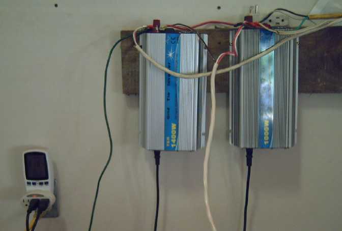 In searching
for something I discovered I had an unused 1400 watt plug-in grid tie
inverter on the shelf. How could I have forgotten? And I had a couple
of poorly functioning ones in use.
On August 1st I put the new one in the cabin, replacing a
1000 watt one whose fans never ran, and which consequently continually
shut off on overheat. Daily energy from the cabin went up. Then I took
the one without fans and put it in the carport where one of the 700
watt grid ties seemed to work rarely if at all. Daily energy from the
carport went up.
I also ordered another AC power monitor.
The weather cooperated beautifully: August 1st to 8th were
sunny and warm, even hot, with the improvements making for 25 KWH days.
Since I'm making the 36 volt cabin pretty much "off grid"
with just one wall outlet where the grid ties plug in, it would be nice
to put a couple more solar panels on the roof to make it six, to work
those grid ties harder and (especially) to have more charge capacity
for the battery. But it's not the best place for panels as it is mostly
in tree shade in the winter months. For overall collection I'd be
better off to put two more on the carport instead. (I could of course
do both? I do have the panels.)
The Usual Daily/Monthly/Yearly Log
of Solar
Power Generated [and grid power consumed]
(All times are in PST: clock 48 minutes ahead of local sun
time, not
PDT which
is an hour and 48 minutes ahead. (DC) battery system power output
readings are reset to zero
daily (often just for LED lights, occasionally used with other loads:
Chevy Sprint electric car, inverters in power outages or other 36V
loads), while the
grid tied readings are cumulative.)
Daily Figures
Notes: House Main
meter (6 digits) accumulates. DC meter now
accumulates until [before] it loses precision (9.999 WH => 0010
KWH), then is
reset. House East and Cabin meters (4
digits) are reset to 0 when they get near 99.99 (which goes to "100.0")
- owing to loss of second decimal precision.
Km = Nissan Leaf electric car drove distance, then car was charged.
New Order of Daily Solar Readings (Beginning May 2022):
Date House, House, House, Cabin => Total KWH Solar [Notable
power
Uses (EV); Grid power meter@time] Sky/weather
Main
DC East
(carport)
After 5 full years (March 2019 to February 2024), I am no
longer recording solar
collection figures daily. (Frequently, and surely monthly.) For the
chart, a figure for "n" days will usually be divided by "n" and taken
evenly as
"n" [more] days of whatever the result is. Oh... now with the DC system
running an electric heater at night (From April 11th 2024), I'm
interested to do daily again for now.
June
30th 1628.30, 6.40, 70.13, 29.06 => 8.26 [40Km; 15776@20:30]
July
1st 1631.76, 7.26, 72.71, 32.41 => 10.92 [45Km; 15790@21:00]
2d 1635.72, 8.76, 76.02, 36.43 => 12.79 [15797@21:00]
3rd 1642.16, 2.00, 80.54, 41.42 => 17.95 [15802@21:30]
4th 1551.25, 3.94, 88.01, 47.93 => 25.03 [15808@20:39]
5th 1560.24, 5.74, 91.55, 54.59 => 20.99 [85Km; 15824@23:00]
6th 1669.76, 7.09, 97.11,
60.97 => 22.81 [55Km; 15836@21:00;
50Km]
7th 1678.80, 8.93, 5.30, 66.92 => 22.13 [35Km;
15849@20:30]
8th 1688.14, 1.90, 10.87, 73.49 => 23.38 [15854@20:30]
9th 1697.53, 3.53, 16.42, 80.23 => 23.31 [55Km; 15866@20:30]
10th 1701.36, 5.04, 19.46, 83.96 => 12.11 [15872@21:00]
11th 1704.51, 6.64, 22.19, 87.20 => 10.72 [40Km; much laundry;
15889@20:30]'
12th 1710.42, 8.53, 26.40, 92.15 => 16.96 [15897@20:30]
13rd 1715.98, 9.78, 30.51, 96.68 => 15.45 [60Km; 15916@22:30; 55Km]
14th 1723.34, 1.71, 36.07, 6.01 => 20.64 [35Km;
15930@'24:00']
16th 1732.58, 4.10, 42.49, 13.27 => 25.31 {est as: 12.66,12.65}
[55Km; 15950@21:00] 2 days
19th 1743.58, 6.20, 49.57, 20.78 => 27.69 {est: 7.60,7.60,12.49:
rain, rain, cloudy} [{0,55,90Km}; 15993@22:00] 3 days
20th 1751.98, 6.34, 53.82, 25.33 => 17.34 [55Km; 16007@21:00; 50Km]
23rd 1771.87, 7.03, 64.26, 37.70 => 43.39 {14.46, 14.46,
14.47}[50Km, 55Km (21st,22nd), 3x
laundry (23rd); 16045@20:30] 3 days
24th 1778.54, 7.13, 67.73, 41.93 => 10.47 [55Km; 16060@22:00]
25th 1782.60, 7.63, 69.95, 44.74 => 9.59 [16067@20:30]
26th 1786.16, 7.76, 71.74, 47.09 => 7.83 [90Km; 16088@20:30]
27th 1788.22, 8.22, 73.52, 49.16 => 6.37 [55Km;
16105@20:30; 50Km]
28th 1790.37, .60, 75.17, 51.10 => 6.37
[35Km; 16126@20:30]
29th 1795.62, .88, 79.02 ,54.96 => 13.18 [16136@21:00] Still
not much like summer!
30th 1799.09, .98, 81.65, 57.93 => 9.17 [16145@22:00]
31st 1802.52, 1.24, 84.21, 61.00 => 9.32 [55Km;
16162@23:00]
August - Wow, suddenly, sunny days!
1st 1809.67, 1.37, 89.72, 66.98 => 18.77 [16167@20:30] Changed a
couple of grid ties - carport & cabin should increase slightly.
2d 1819.11, 1.49, 96.04, 74.75 => 23.65 [85Km;
16182@20:00] found one turned off at house, midday!
3d 1830.54, 1.63, 6.03, 82.68 => 25.53
[55Km; 16196@21:00; 50Km]
4th 1841.88, 1.81, 11.80, 90.56 => 25.17 [45Km; 16208@21:30]
5th 1852.83, 1.88, 18.25, 97.78 => 24.69 [16213@21:00]
6th 1863.92, 1.98, 24.80, 7.39 => 25.13
[16218@20:30]
7th 1872.92, 2.13, 30.96, 13.51 => 21.43 [55Km; 16228@21:00]
Foggy AM. Ate first corn cob!
8th 1883.93, 2.27, 36.81, 21.15 => 24.64 [16236@21:00]
9th 1889.64, 2.40, 40.50, 24.67 => 13.05 [85Km; 16254@20:30]
Not sunny. (Was great while it lasted!)
Chart of daily KWH from solar panels.
(Compare July 2024 with June 2024 &
with July 2023.)
Days of
__ KWH
|
July 2024
(18 Collectors)
|
June 2024
(18 C's)
|
July 2023
(18 C's)
|
0.xx
|
|
|
|
1.xx
|
|
|
|
2.xx
|
|
|
|
3.xx
|
|
|
|
4.xx
|
|
|
|
5.xx
|
|
|
|
6.xx
|
2
|
|
1
|
7.xx
|
3
|
|
1
|
8.xx
|
|
2
|
2
|
9.xx
|
3
|
1
|
|
10.xx
|
3
|
|
1
|
11.xx
|
|
1
|
2
|
12.xx
|
5
|
3
|
|
13.xx
|
1
|
5
|
2
|
14.xx
|
3
|
3
|
2
|
15.xx
|
1
|
|
|
16.xx
|
1
|
5
|
2
|
17.xx
|
2
|
2
|
1
|
18.xx
|
|
1
|
3
|
19.xx
|
|
1
|
|
20.xx
|
2
|
1
|
2
|
21.xx
|
|
|
1
|
22.xx
|
2
|
2
|
1
|
23.xx
|
2
|
2
|
3
|
24.xx
|
|
|
2
|
25.xx
|
1
|
1
|
3
|
26.xx
|
|
|
1
|
27.xx
|
|
|
1
|
Total KWH
for month
|
444.56
|
420
|
563.61
|
Km Driven
on Electricity
|
~1265.8 Km
165 KWH
|
~1465 Km
190 KWH
|
1348.1 Km
(180 KWH?) |
Things Noted - July 2024
* Nothing special. Weather not very nice (clouds, damp, rain) for last
1/3 of month.
Monthly Summaries: Solar Generated KWH [& Power used
from
grid KWH]
As these tables are getting long, I'm not repeating the log of monthly
reports. The reports for the first FIVE full years (March 2019 to
February 2024) may be found in TE
News
#189,
February
2024.
2024
Jan KWH: 31.37 + 3.14 + 16.85 + 16.82
= 68.18 [grid: 909; car (very rough estimates): 160]
Feb KWH: 96.52 + 2.36 + 49.67 + 52.98 = 201.53
[grid: 791; car: 130]
FIVE full Years of solar!
Mar KWH 150.09+ 1.63 + 93.59 + 92.50 = 337.81 [grid: 717; car:
140]
Apr KWH 181.89+35.55 +123.50+142.74 = 483.68 [grid: 575; car: 140]
May KWH 129.23+67.38 +109.6 +126.32 = 432.53 [grid: 405; car: 145]
Jun KWH
152.54+51.02+118.99+141.17 = 463.72 [grid: 420; car: 190]
July KWH 174.22+30.53+111.19+128.62 = 444.56 [grid: 386; car: 165]
Annual Totals
1. March 2019-Feb. 2020: 2196.15 KWH Solar [used 7927 KWH
from grid; EV use: -] 10, 11, 12 solar panels
2. March 2020-Feb. 2021: 2069.82 KWH Solar [used 11294 KWH from grid;
EV use: -
(More electric heat - BR, Trailer & Perry's RV)] 12 solar panels
3. March 2021-Feb. 2022: 2063.05 KWH Solar [used 10977 KWH from grid;
EV use ~~1485 KWH] 12 solar panels, 14 near end of year.
4a. March 2022-August 2022: in (the best) 6 months, about 2725 KWH
solar - more than in any previous entire year!
4. March2022-Feb. 2023: 3793.37 KWH Solar [used 12038 KWH from grid; EV
use: ~1583 KWH] 14, 15, 18 solar panels
5. March 2023-Feb. 2024: 3891.35 KWH Solar [used 7914 KWH from power
grid; EV use: ~1515 KWH] 18 solar panels
Money Saved or Earned - @ 12¢ [All BC residential elec.
rate] ; @ 50¢ [2018 cost of diesel fuel to BC Hydro] ; @ 1$ per
KWH [actual total cost to BC Hydro in 2022 according to an employee]:
1. 263.42$ ; 1097.58$ ; 2196.15$
2. 248.38$ ; 1034.91$ ; 2069.82$
3. 247.57$ ; 1031.53$ ; 2063.05$
4. 455.20$ ; 1896.69$ ; 3793.37$
5. 466.96$ ; 1945.68$ ; 3891.35$
It can be seen that the benefit to the society as a whole
on Haida Gwaii from solar power installations is much greater than the
cost savings to the individual user of electricity, thanks to the heavy
subsidization of our power owing to the BC government policy of having
the same power rate across the entire province regardless of the cost
of production. And it can be insurance: With some extra equipment and a
battery, sufficient solar can deliver essential power in electrical
outages however long. (Feb 28th 2023: And it's probably well over
1$/KWH by now the way inflation of diesel fuel and other costs is
running.)
It might also be noted that I never went into this in a
big way. Instead of installing a whole palette load of 32 solar panels,
I have 18, and my grid ties aren't the best, and I would be hard put to
give an accurate total of my installation costs. All in all the grid
tied part probably cost me (with all my own 'free' labor) around 7000$.
At the actual "total savings to all" figures, they have paid for
themselves twice over in five years. The 36V DC system largely cost a
couple of thousand dollars for batteries. The solar panels were up. The
charge controller, circuit breakers, DC combo meters [V, A, W, WH], 36V
compatible LED lights and wiring cost were a few hundred dollars at
most. (I did have to make my own T-Plug cables & 3D printed wall
plates.) The battery cost has come down substantially in recent years
and will come down a lot more if I can get cheap, "forever cycle"
batteries working.
http://www.TurquoiseEnergy.com
Haida Gwaii, BC Canada


 I continued adding to the surface
mounted wiring board. I installed the ground bus made in June. I 3D
printed a four-outlet wall plate to plug
several ceiling lights into rather than hard-wiring them. I suppose one
could fit 5 or 6 T-sockets on one wall plate. No "power bars" to get
enough outlets!
 On the 10th I wired up a wall receptacle in the upstairs room. I took
off a piece of gyproc from under the window and screwed in an
electrical box. Underneath, the walls are still open and stringing the
wire through the 2 by 4s by drilling holes was easy.
 I used #14-3
cable, which is actually four wires counting the #14 bare "ground"
wire. I tied red and white together ("+"), and the black and the
bare after insulating it (two blacks, "-"), and tied them to the
pigtails soldered onto
the T-Plug (36V DC) wall plate. Double #14 AWG is the same as #11 -
good for about 25 amps. #12-2 (rated 20 amps) would be fine for 36 volt
- 20 amp outlets, too. #14-2 is a bit thin.
 In early August I used the new outlet and a "double T-Plug" I made a
while back to power a
2500 W PSW inverter (36 VDC to 120 VAC) and vacuumed the room on
solar/battery power. The
double plug wanted to pull out at the slightest stress on the heavy
wires. (The "giant T-Plug" for
high currents is the real answer... but they need to be manufactured.)
 And I created
a "giant T-Plug" & Socket for currents to 50 amps. These are harder
because everything is made from scratch - they need to be manufactured.
But manufacturing keeps getting easier as new techniques and tools are
created. (...and I must upload all the 3D print designs to
thingiverse.com for all to use!)
 Now that LED's
have replaced most other
lighting technologies, DC lights are simple. LED's
are inherently low voltage DC components (generally 2.9V for lighting
LED emitters. A fast, simple way to get nice DC lamps is to take a nice
AC lamp, cut the plug off, and put on a 12V or 36V plug. Then one buys
a DC LED "light bulb" that screws into a regular ("E27") lamp socket.
There are "12V" bulbs, and there are "12 to 72V" bulbs, which are
ideal at 36V. (Note: These last are dimmer - lower power than labeled -
when run
at 12V.)
 Most off-grid installations will have
trouble supplying such higher-powered devices for extended periods. (Of
course "on grid" buildings could use the AC to drive a heavy 36 V DC
power supply and run all the DC things they wish at low voltage DC.) It
is especially desirable to keep AC wiring away from bedrooms (along
with WiFi and cell phones) for health reasons. Many people don't give
their bodies many breaks from such mild but eventually deleterious
emissions.
 I
also made a "double T-Plug" idea for heavier circuits, maybe 15 or 20
to about 30 amps. I thought it would be good because it uses the same
T-Plugs & Sockets. Frankly I don't think I recommend this, but it
consists of two T-Plugs/T-Sockets beside each other exactly 12mm apart.
I spaced some wall outlets that way and made shells to hold the T-Plugs
at that spacing.
I
also made a "double T-Plug" idea for heavier circuits, maybe 15 or 20
to about 30 amps. I thought it would be good because it uses the same
T-Plugs & Sockets. Frankly I don't think I recommend this, but it
consists of two T-Plugs/T-Sockets beside each other exactly 12mm apart.
I spaced some wall outlets that way and made shells to hold the T-Plugs
at that spacing. For said wall
outlet I ran a #14 AWG - 3 wire cable from the DC "wiring closet" under
the stairs straight to the outlet box. Since the bare "ground" wire is
also #14, that makes four wires. The way "AWG" works, the diameter of a
wire is half of one three gauges down. This means that two #14 AWG
wires together have the same cross section as a single #11. Best
breaker rating for #11 would be 25 amps, allowing up to 900 watt
appliances to be plugged in.
 I used a
moderately deep box for the wires plus the sockets to fit into.
 When I put the
wall plate on I discovered the box stuck way out of the wall. Oops!
 The end of the second set of ceiling sheets didn't quite
reach the last rafter, with this one central rafter gap being more than
24 inches wide. What to do? I finally opted for screwing in a 2 by 2
onto the side of the rafter an inch above the bottom, then screwing a 1
by 8 to that, horizontal, so it was flush with the bottom of the
rafter. That gave
10 inches width to screw ceiling panels to.
 [14th] I
finally got the nerve and put on crappy old clothes to
continue insulating the upstairs room ceiling. It was even worse than I
expected. I finally used the last loose pieces of R28 insulation I got
used, but the "new" bag was just as bad. It was hard to tell where one
so-called "batt" ended and the next began - they all just stuck
together almost as if one big fat piece. Whenever it was touched,
clouds of very fine dust came off it, and bigger bits continually fell
off like snow. Not only would it not stay put in the ceiling spaces
between the rafters, but it would hang from a string like a limp towel.
In the lower parts I could put in strips of plastic and then slide the
"batts" in, but I had to string the top part. I used some old twine and
roofing nails to hold it once in place.
 This
particular
insulation reminded me of some from 1976-77 when manufacturers had
decided to used "recycled glass" to make fiberglass. It turned out that
many fibers were the same shape and size as asbestos, hence were
carcinogenic. I had used that horrid stuff under my house in
1977-78, and this "new" stuff didn't seem any better. What luck! Hmm...
had it lain around all these years since that period? I
finally thought to look for a URL on the packages. If there wasn't one,
it could potentially be that old. There wasn't, but there was a date:
Dec. 2001. Maybe it had degraded over a couple of decades of imperfect
storage?
 Having managed to put in thirteen fiberglass batts and
three sheets of coroplast ceiling, my endurance completely ran out and
I had to leave the last three batts and last sheet for the next morning.
 [17th] I had a double pane
window which had been two parts, one
sliding, one fixed. I had split the double pane and got it out of the
frame successfully (to clean the inside -- in spite of the sticky black
tape/goo). Now I cut the
frame down to use just the fixed part and spent the day roughing it
into
place for the bedroom window. I had to cut a small notch in the rafter
and trim the ceiling a bit,
so it was certainly the biggest window that could fit. I put the frame
in backwards so that I could put in or remove (to clean) the window
glass from inside instead of from the outside on a tall ladder.
 [19th] I
continued sleeping in the cabin. This gave me great incentive to finish
the last wall. I made a bizarre mistake on the framing under the center
beam: the space was 49 inches tall. Four inches had to be subtracted
from the studs for the 2 by 4's, and somewhere overnight my mind had
imprinted "39 inches". I never questioned or verified it so of course
it came out 6 inches too short. I put it up anyway. The top part with
the angles and every post a different length didn't go perfectly
either, but it ended up right.
 I ran the
gyproc verticly, floor to ceiling, which essentially nullified the
framing mistake. I also found I could remove the heavy beam joiner on
the bedroom side, leaving just the one on the other side and here just
bolt ends to be plastered over.
 By mid July
the corn was starting to grow ears! To my
surprise, the ones nearer the back were doing much better than the ones
at the front, some of which had actually died in the spring. Was not
enough light coming in near the front... or did it get colder around
the
edges in the spring? Hmm... There were pretty big cracks around the
edges. I thought they'd be fine, but the stalks in the middle and
toward the back probably
stayed warmer. Next year I'll reuse the same 'greenhouse box' [TE News #191 - scroll to bottom
of "April in Brief"] but close around the edges
better. (And maybe find something that lets more light through for the
sides?)
 My friend Kamil said he had some sweet potatos from the
store that were starting to sprout. I've never seen them sprouting
before, so that was interesting. My brother says he grows them in his
greenhouse in Toronto. But I was sure it was too cool to grow them
here. He reminded me that I had some all-styrofoam cooler box cubes. If
I covered them with a sheet of glass and put dirt in them, the sun
would heat up the dirt and they would stay warm inside.
 In a week they were both sprouted! The dirt
is pretty shallow but can be deepened as they grow, and it will
hopefully fill with tubers. (Now, what about yams? I think they need it
even warmer, but might it be worth a try? I guess I should see how
these do first.)
 The coffee
bushes flowered and started growing new beans. I saw some nice flower
petals but when I finally went to get a picture they were gone.
 [15th] The tube with the
carbon rod weighed 30.90 grams. I added
NiMn2O4(?) powder mix and it was 42.75, so 11.85 grams of mix. Plunging
in the tapered rod and then the tapered carbon rod... and scraping some
out with a screwdriver because the rod wouldn't go in far enough... I
think I got it pretty compacted, and about 10mm below the top. I topped
it up with heat glue.
 Surely I'm stumbling around in the dark. None of the
positive electrodes of whatever chemistry I try seem to have even a
fraction of the amp-hours that I think they ought to, deteriorating
performance, and (except for using cupro-nickel sheet metal), very low
current drive as well. The commercial dry cell nickel oxyhydroxide
worked better than my homemade "+" 'trodes, but not nearly as well as
it did in the original Ni-MH dry cell. What am I missing? Could
it simply be that I couldn't seem to seal the lids to keep air out?
Could a bit of air getting into the electrolyte really matter? After
all, most of the early researchers had open top beakers and jars. But
what if it affects the charging, hour after hour? There was the next
thing to try!
 This nickel pourbaix
diagram suggests
that Ni(OH)3- is formed at pH 13-14. This isn't mentioned in battery
literature. One expects it would saturate at very, very low
concentration. Even
so, it could limit the 'forever' life of the cell if not contained
within the
electrode. So even with nickel, my positives are going to get the full
ion blocking treatments of SDBS in the separator and osmium doping.
 Or!... come to think of it... gold! The alkaline reaction voltage of
nickel to oxyhydroxide is around .5V, gold to gold hydroxide is about
.6V. It doesn't seem like a very big margin of safety, but if it works
and doesn't degrade it would certainly provide high current capacity.
Or even if it oxidizes, if an impenetrable Au(OH)3 layer will form on
the surface at pH 12-13, that would protect it while charging. When
charging stopped that surface would discharge back to Au metal - at
least, as soon as there was a load. (Wait, where was Jungner when he
was testing all the metals and found that "only nickel" didn't oxidize
away? Did he try gold? But he was doing pH 14, and there can still be a
difference between pH12-13 and pH 14.)
 I
found my gold plating solution (from 2019) and tried
plating a small piece of graphite foil. It worked.
 I rubbed one face to
shine it up - and most of the gold rubbed off! The yellow color was
pretty much gone and it only remained in the recessed spaces. I guess
being able to electroplate it doesn't stop graphite from being slippery
and
greasy! There's probably enough bits left to improve conductivity, but
it's disappointing that it comes off so easily. I can't imagine there
being much left if a graphite rod is jammed into an electrode and
twisted to compact the powders... and to get good connection.

 [Back to 23rd] When
connections &c are good, charging day after day
seems to be improving it. With a 50 Ω test in the afternoon, in the
1.75X range, the drop rate was down to about 8 mV/minute, way under
half what it had been a couple of days previous. Then it slowed down.
It finally hit 1.700V after 22'. 40' - 1.661V. I noticed current was a
bit low for the voltage - not by much, maybe 6-10%. I fiddled with an
alligator clip and flipped the switch a couple of times. Yup, that was
it. 27mA went to 29. 1.6V, 50Ω = you'd expect 32mA, but it's never
quite as high as expected. 50' - 1.642V. So it's only dropping about
2mV/minute. Great! This is cutting into my nap time again!
 A footnote is
that after changing the electrolyte, and
with trodes that are no longer brand new, there's still black stuff
accumulating on the bottom of the jar. Either a tube is leaking or
substance is dissolving out and then solidifying and precipitating out.
I see greenish (& black) nickel oxide or hydroxide in the holes in
the pipe wall. Probably it's outside the separator sheet. Likely
Ni(OH)3- ions, spontaneously converting to NiOOH(black)+H2O? Hopefully
if I put osmium dopant on the inside surface of the sheet it'll prevent
the penetration and the conversion. Hopefully. (The zinc also has a bit
of black around the holes, but I don't think it's emitting
anything. If it is, well, it's not the latest design.)
 On a whim I
put it into the same jar cell, simply
disconnecting the Ni(OH)2 electrode and subbing the new NiO one. I left
it a few minutes to soak. After the load test, the zinc couldn't be
fully charged, so it couldn't be blamed if charging current was low.
Sure enough, charging current soon dropped to 9mA anyway, and a quick
load test was quick because it only ran for 50".
 I extruded a
nice donut and to my surprise it slid off the inner bolt easily, so it
had a hole for a carbon rod. I tried again using a bigger spoonful of
powder to make a longer one. This one worked but had a lot of loose
powder around it. If the original scoop of powder extended past the
inner bolt, that would happen. Also the tube wasn't quite small enough
inside, so there was a bit of a gap around the bolt. I'd like to do
something about that. Enough for today!

 In searching
for something I discovered I had an unused 1400 watt plug-in grid tie
inverter on the shelf. How could I have forgotten? And I had a couple
of poorly functioning ones in use.